Download
1 / 25
250 likes | 600 Views
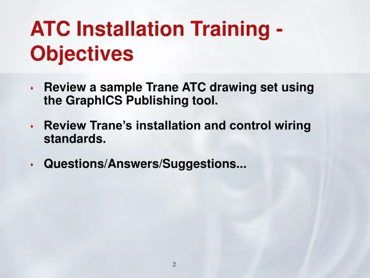
ATC Installation Training - Objectives. Review a sample Trane ATC drawing set using the GraphICS Publishing tool. Review Trane’s installation and control wiring standards. Questions/Answers/Suggestions. Trane ATC Drawing Sets.

E N D
ATC Installation Training - Objectives • Review a sample Trane ATC drawing set using the GraphICS Publishing tool. • Review Trane’s installation and control wiring standards. • Questions/Answers/Suggestions...
Trane ATC Drawing Sets • Current drawing sets are published in GraphICS. GraphICS is a Trane-proprietary drawing utility that is distributed for use company-wide.
Lycoming Student Housing – Title Block SHEET DATE/REVISION NUMBER SHEET DESCRIPTION
Lycoming Student Housing – Drawing Index IDENTICAL TO DRAWING TITLE ON EACH SHEET
Lycoming Student Housing - General Installation Instructions SYMBOLS GENERAL NOTES CABLE INFO CABLE SHAPES
Wiring Notes are the generally accepted installation procedures for all ATC installation. These are discussed in more detail later in the presentation. Lycoming Student Housing - Wiring Notes
Cable type designated by alphabetical letters. Not all types used on every project. Lycoming Student Housing - Cable Matrix and Information
Damper and Valve Schedules provide information for the Mechanical Contractors and performance data. Lycoming Student Housing - Damper and Valve Schedules
Comm Riser shows both Cat 5 to BCU and Comm Links to Unit Controllers. Order of controllers on the links is schematic-only, best guess. Lycoming Student Housing - Comm Link Riser Diagram DEVICE TAG SERVICE DESCRIPTION MOUNTING LOCATION
Lycoming Student Housing – BCU/BMTX Wiring Detail TERMINATION INFO LINK DESTINATION CABLE TYPE
Schematic line drawing of the piping system and components. Control end devices first appear on this sheet (cabling/BOM). Lycoming Student Housing – Water System Schematic
Field wiring details will be shown after the schematic page for more complicated control wiring. (Relay logic, safety circuits, interfaces, etc.) Lycoming Student Housing - Water System Wiring Details
Sequence will appear either on the system/unit flow schematic, or on a separate page following the schematic. Lycoming Student Housing Water System Sequence
Controller detail matches end device to correct point termination using the cable number. Comm link terminations also shown here. Example: Cable 152 on schematic is cable 152 on controller detail. Lycoming Student Housing – Water System Controller Detail POINT DESCRIPTION CABLE TERMINATION END DEVICE DETAIL (SHEET 28, DETAIL B) CABLE NUMBER
End Device Detail sheets are located at the end of the drawing set. They show cable terminations on the end device (wire colors, terminal numbers, etc.). Lycoming Student Housing - End Device Detail Sheets SHEET NUMBER
Communication Wire Comm 3 or Comm 4 wire type, BACnet MS/TP wiring (future) 18ga./2c., Purple, twisted-shielded pair, plenum-rated, 25 pF/ft capacitance Maximum total link length of 5000 feet, No termination resistors required Windy City Wire Part Number – 051001 or approved equal Comm 5 wire type (Lon compliant Level 4 wire) 22ga./2c., Blue, twisted-unshielded pair, plenum-rated, 17 pF/ft capacitance Maximum total link length of 4500 feet, 105 Ohm End-of-Link Resistors Windy City Wire Part Number - 105500 or approved equal ATC Installation Training – Installation and Control Wiring Standards
Comm Link Installation Best Practices. Keep track of communication link daisy chains on mechanical plans and turn over to Trane technician when equipment check out begins. (This must be recorded on any job with a comm link, no exceptions.) Do not mix comm wire types. Trane Purple comm wire (18/2 shielded) may have been used on previous installations for Comm 5 links. If adding new devices to those links you must continue using the Purple comm wire (18/2 shielded) and 82 Ohm end-of-link resistors. Comm 3, Comm 4, and BACnet MS/TP (future) devices require DIP switch settings for addressing. Addresses are set by the ATC installer. Addressing information is found in the ATC submittal. Addressing tables are provided on each unit. Comm 5 (Lon) devices have a unique hexadecimal address called an Neuron ID address (NID). (e.g. 04.D1.1E.58.02.00) Trane controllers are provided with stickers listing the NID address. The sticker should be placed in the ATC drawing set either on the Equipment schedule or controller point schedule. ATC Installation Training – Installation and Control Wiring Standards
Control Point Wiring Standards All Binary/Analog Outputs and Inputs should be run with 18 AWG, plenum rated, shielded, stranded, tinned copper conductors. Multi-conductor cable is acceptable, but AI and BO wires should be run in separate cables. AO (0-10VDC & 4-20mA) must not exceed 1000ft. BO (24VAC) must not exceed 1000ft. BI must not exceed 1000ft. AI (resistance & 0-10VDC) must not exceed 300ft. AI (4-20mA) wiring must not exceed 1000ft. All standard point wiring must be plenum rated. If running plenum wire, avoid running wire near lighting ballasts, especially 277VAC. ATC Installation Training – Installation and Control Wiring Standards
Controller Mounting Best Practices. Controllers should be mounted as indicated on the ATC drawings, mechanical plans, or a location approved in the field by a Trane representative. Controllers should be mounted so that they are easily accessible. Controllers with User-displays should not require a ladder to access. Controllers without User-displays should be reasonably accessible within ladder-height of 6-8 feet. Controllers mounted above drop ceilings should be mounted in common accessible areas (corridors, etc.). Mark ceiling grid close to controller with sticker/tag/etc. Avoid mounting controllers in bathrooms, locker rooms, private offices, etc. Label controller front cover with device tag as indicated in the ATC drawings. (e.g. AHU-1 MP581-1) On controller backplanes, label in permanent ink the controllers power source (transformer or circuit breaker). ATC Installation Training – Installation and Control Wiring Standards
Control Power and Transformer wiring. Mount control power transformers at the primary-side voltage source or hub mount directly to the controller it is powering. For multiple transformers at one primary power source, mount all transformers in one junction box of appropriate size. BCU/BMTX control power and phone line wiring must be protected from power surges. The surge arrestors (Transtector TR2255 and TR2256) or a Back-up Battery Pack provided by Trane with the BCU/BMTX must be installed next to the BCU/BMTX in a junction box. Mount 120VAC power outlet (2-outlet box) next to BCU/BMTX for service use (Laptop, Ethernet hub, etc.). ATC Installation Training – Installation and Control Wiring Standards
Sensor mounting notes. Room thermostats/sensors. Seal all wall penetrations behind room thermostats/sensors with silicon sealant. Mount thermostat/sensor on a wiremold standoff (Trane provided) for concrete walls and exterior walls. When wiremold standoff is used, fill standoff void behind sensor with foam insulation. Verify mounting height of sensors with a Trane Project Manager before mounting. Outside air temperature/humidity sensors. Mount sensor on north side of building, under roof overhang or fabricated sunshield. Coordinate final location with a Trane Project Manager. Do not mount near exhaust air sources. Fill conduit entering back of sensor with foam insulation. ATC Installation Training – Installation and Control Wiring Standards
Polytube installation notes. Label both ends of polytube as indicated on ATC drawings or with end device tag. Install duct static tips and space static pick-ups where indicated on the ATC drawings, coordinate with Trane Rep if unclear. Wiring miscellaneous notes. Label both ends of control wires with tag indicated on the ATC drawings or with end device tag and controller point. For multiple end devices in one location (relays, DPT’s, etc.), request a NEMA enclosure from Trane before mounting. Keep field copy of ATC drawing set updated with any wiring changes in field and give to Trane technician when job is being checked out. ATC Installation Training – Installation and Control Wiring Standards
Questions? Comments? Suggestions? ATC Installation Training –
Thank You for Attending. ATC Installation Training –