Download
1 / 5
50 likes | 138 Views
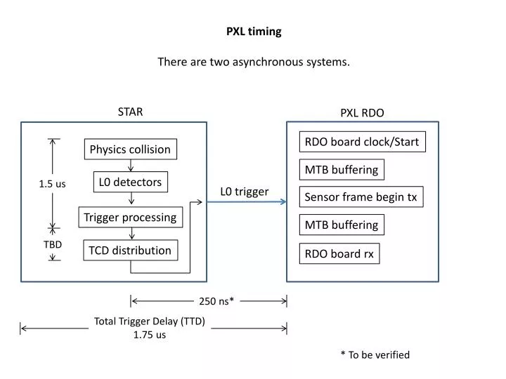
PXL timing There are two asynchronous systems. STAR. PXL RDO. RDO board clock/Start. Physics collision. MTB buffering. L0 detectors. 1.5 us. L0 trigger. Sensor frame begin tx. Trigger processing. MTB buffering. TBD. TCD distribution. RDO board rx. 250 ns*.

E N D
PXL timing There are two asynchronous systems. STAR PXL RDO RDO board clock/Start Physics collision MTB buffering L0 detectors 1.5 us L0 trigger Sensor frame begin tx Trigger processing MTB buffering TBD TCD distribution RDO board rx 250 ns* Total Trigger Delay (TTD) 1.75 us * To be verified
PXL RDO PLAN • Use an oscilloscope to measure the transit time from the START generated on the RDO board to the receipt of the START on the low mass cable section. • Add the time from the Ultimate manual from the receipt of START to the first row processing. • The time offset between the send of START from the RDO motherboard (internal time pointer) and the beginning of the first row processing is then TD + FPD • This will be done with the production cables, MTB and feedthrough. Send start Ladder sensor PXL RDO tx MTB buffering Transit Delay (TD)
LVDS measured on one side of termination resistor. Blue trace – Falling edge of START measured at RDO board R34 Yellow trace – START (opposite polarity) measured on driver board R95 Transit Delay = 79 ns
PXL initial startup timing Send start PXL RDO tx MTB buffering Ladder sensor Delay until frame starts Ladder sensor First frame latency Delay until past frame header MTB buffering RDO board rx Sensor frame begin tx RDO board Serdes processing We will measure the full latency through the system from the transmission of the START to the arrival of the first frame header at the RDO board
LVDS measured on one side of termination resistor. Blue trace – falling edge of START measured at RDO board R34 Yellow trace – Sensor1 data output 1 (opposite polarity) measured on RDO board R1. First frame latency = 7.093 us