Download
1 / 56
570 likes | 698 Views
Basics Of Electricity. History. HISTORY OF ELECTRICAL POWER SYSTEMS Thomas A. Edison , Father of electric light in 1882 Frank Julian Sprague , Produced dc motor for Edison systems in 1884 Nikola Tesla , Father of two-phase ac induction and synchronous motors in 1888

E N D
Basics Of Electricity Basics Of Electricity Seminar
History • HISTORY OF ELECTRICAL POWER SYSTEMS • Thomas A. Edison, Father of electric light in 1882 • Frank Julian Sprague, Produced dc motor for Edison systems in 1884 • Nikola Tesla, Father of two-phase ac induction and synchronous motors in 1888 • William Stanley, Father of commercially practical transformer 1885/86 Basics Of Electricity Seminar
Witam wszystkich zebranych na seminarjum poświęconym podstawom elektryczności… • Well, I know sometimes it feels like we speak foreign language… • And sometimes even simple concepts are presented in a quite confusing way… • I hope that this presentation will help you to understand electricity and make selling Amprobe products easier Basics Of Electricity Seminar
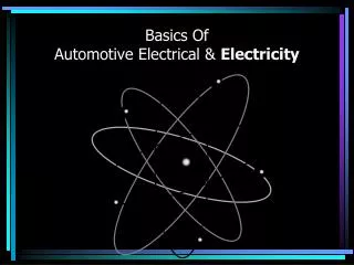
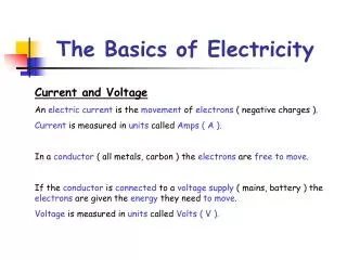
Basics Electrons Electrons are the smallest and lightest of the particles in an atom. Electrons are in constant motion as they circle around the nucleus of that atom. Electrons are said to have a negative charge, which means that they seem to be surrounded by a kind of invisible force field. This is called an electrostatic field. Protons They are much larger and heavier than electrons. Protons have a positive electrical charge. This positively charged electrostatic field is exactly the same strength as the electrostatic field in an electron, but it is opposite in polarity. Notice the negative electron and thepositive proton have the same number of force field lines in each of the diagrams. In other words, the proton is exactly as positive as the electron is negative. Basics Of Electricity Seminar
Basics • Like charges repel, unlike charges attract • Two electrons repel each other because both have a negative electrical charge. • Two protons repel each other because they both have a positive charge. • Electrons and protons attract each other because of their unlike charges. Basics Of Electricity Seminar
Voltage • Mathematical definition • The electrical potential difference is defined as the amount of work needed to move a unit electric charge from the second point to the first, or equivalently, the amount of work that a unit charge flowing from the first point to the second can perform. The potential difference between two points a and b is the line integral of the electric field E: Basics Of Electricity Seminar
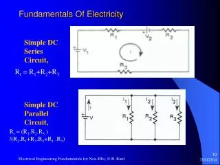
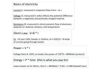
Basic Electric Circuit • E – Voltage (V) • I – Current (A) • R – Resistance (Ω) I V R Basics Of Electricity Seminar
Ω (Ohm) - Resistance I - current Air Flow Air Valve Air tool Pressure Air tank V - voltage Volts, Amps, Ohms – Simple! Basics Of Electricity Seminar
Basics • VOLTAGE (V) • Voltage is the difference of electrical potential between two points of an electrical circuit, expressed in volts. • Electromotive force, or EMF - the force that causes the electrons to move in an electrical circuit . • An electric potential difference must exist for current to flow in an electric circuit. • VA - VD = 12 - 0 = 12 V Basics Of Electricity Seminar
Basics • Electrical Current and Amperage (A) • Electrical Current is defined as a flow (movement) of electrons. • Current is measured in units called Amperes or Amps. • Amperageis a term used to describe the number of electrons moving past a fixed point in a conductor in one second. • Since we cannot count electrons by hand, we need an Ammeter, the instrument measuring the electrons flow Basics Of Electricity Seminar
Basics • Resistance • Resistance - measured in units called Ohms (Ω) . • It describes the forces that oppose the flow of electron current in a conductor. • All materials naturally contain some resistance to the flow of electron current, some more, some less… Symbol Formula where L represents the length of the wire (in meters), A represents the cross-sectional area of the wire (in meters2), and ρ represents the resistivity of the material (in ohm•meter). Basics Of Electricity Seminar
Basics • Resistance • Is resistance good or bad? • It can be both good and bad. If we want to transmit electricity from one place to another through a conductor, resistance is undesirable in the conductor. It causes some of the electrical energy to turn intoheat. • However, it is resistance that allows us to use electricity for heat and light. The heat that is generated from electric heaters or the light that we get from light bulbs is due to resistance. Basics Of Electricity Seminar
Basics Conductors and Insulators • Conductors - materials that have free electrons and allow electrical current to flow easily (e.i. copper, aluminum). These materials have LOW resistance for electric current. • Insulators - materials that do not have free electrons (e.i. glass, plastic, rubber, air). They have HIGH resistance for electric current. • Insulators are used to protect us from the dangerous effects of electricity flowing through conductors. Basics Of Electricity Seminar
Basics • Electromagnetic fields • The term electromagnetism is defined as the production of a magnetic field by current flowing in a conductor. • The magnetic field around the conductor flows in closed loops. Basics Of Electricity Seminar
Basics • Field Intensity • The term field intensity is used to describe the strength of the magnetic field. • Field intensity is determined by the amount • Of current flowing in the wire. • “The right-hand rule” is the simplest way • To determine the direction of the • electromagnetic field Basics Of Electricity Seminar
Quiz • Who invented the light bulb? In addressing the question "Who invented the incandescent lamp?" historians Robert Friedel and Paul Israel list 22 inventors of incandescent lamps prior to Swan and Edison. They conclude that Edison's version was able to outstrip the others because of a combination of factors: an effective incandescent material, a higher vacuum than others were able to achieve and a high resistance lamp that made power distribution from a centralized source economically viable. Basics Of Electricity Seminar
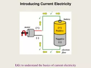
AC / DC In the DC circuit current flows in one direction. On the other hand the AC power sources “pump” current “back and forth”. Basics Of Electricity Seminar
AC vs. DC signal Basics Of Electricity Seminar
RMS (don’t confuse with True RMS!) Basics Of Electricity Seminar
Distorted Sinewave… • If we use a standard average sensing meter on a distorted sine wave the measuring error can reach over 30% (usually these meters tend to measure lower). So instead of displaying 120V at the receptacle, you may read as low as 90V! This is a huge measuring error! Basics Of Electricity Seminar
RMS vs. True RMS devices • RMS devices use various methods of approximating RMS value. These methods work well for purely sinusoidal signals (ideal world), but they will give erroneous results when measuring distorted signals (real world). Example: average sensing meter. • True RMS devicesuse a more accurate and robust method that gives better measurements of distorted signals. • Accurate measurement is essential for proper design and maintenance of electrical networks (inaccurate measurement leads to underutilization or overloading). Basics Of Electricity Seminar
Capacitance • A capacitor is an electrical/electronic device that can store energy in the electric field between a pair of conductors (called "plates"). The process of storing energy in the capacitor is known as "charging", and involves electric charges of equal magnitude, but opposite polarity, building up on each plate. • Capacitors are often used in electric and electronic circuits as energy-storage devices. They can also be used to differentiate between high-frequency and low-frequency signals. This property makes them useful in electronic filters. • Capacitance is a measure of the amount of electric charge stored (or separated) for a given electric potential. • The SI unit of capacitance is the farad; 1 farad = 1 coulomb per volt. Basics Of Electricity Seminar
Inrush Current • Inrush current or input surge current refers to the maximum, instantaneous input current drawn by an electrical device when first turned on. • AC electric motors and transformers may draw several times their normal full-load current when first energized, for a few cycles of the input waveform. Basics Of Electricity Seminar
Duty Cycle • Duty cycle is the proportion of time during which a component, device, or system is operated. • Suppose a disk drive operates for 1 second, and is shut off for 99 seconds, then is run for 1 second again, and so on. The drive runs for one out of 100 seconds, or 1/100 of the time, and its duty cycle is therefore 1/100, or 1 percent. • D - duty cycle; • τ - duration that the function is non-zero; • Τ - period of the function. Basics Of Electricity Seminar
Temperature Where Gabriel Fahrenheit was Born? • German physicist Gabriel Fahrenheit was born in Gdansk (Danzig), Poland What reference Fahrenheit used to establish 0 degrees on his scale? There are a few competing versions of the story. One of them states that Fahrenheit recorded the lowest outdoor temperatures he could measure during harsh winter of 1708 through 1709 in his hometown of Danzig (now Gdańsk, Poland) (−17.8 °C) as his zero point. He was later able to reach this temperature under laboratory conditions using a mixture of ice, sodium chloride and water. Basics Of Electricity Seminar
Voltage & current basics – amplitude, frequency and RMS. • Amplitude (Peak) – the maximum magnitude of a periodic waveform. • Frequency – number of cycles per unit time (per second = Hz). Basics Of Electricity Seminar
Voltage amplitude disturbances • Sag/swell – decrease/increase in voltage value for a short period of time (~1/2 cycle to 1 minute). • Spike – very short-duration (microsecond to millisecond), high-amplitude (maximum of 200V to 6000V) change in voltage. These can be disastrous for unprotected, sensitive electronic equipment. Basics Of Electricity Seminar
Three-Phase systems • Two main types in the US called Delta and Wye • Delta system (3-Phase 3-Wire) named after the schematic resemblance of the windings to the Greek letter Delta • three independent transformer or generator windings that are connected head to toe - no single point common to all phases. • Single voltage level available - the Phase to Phase voltages. • Other voltages can be obtained only by using step-up or step-down transformers. • Wye system (3-Phase 4-Wire) named after the schematic resemblance of the windings to the letter Wye ( Y ) • three, independent transformer or generator windings that are connected at a common point, called a neutral or star point. • Wye connected power has two different voltages available. • The Phase to Phase voltage is the main system voltage (typically 208 VAC or 480 VAC in the United States). • The Phase to Neutral voltage is also available, and is typically used for small single phase loads (120 VAC or 277 VAC) Basics Of Electricity Seminar
Three-Phase systems • In a three-phase system, three circuit conductors carry three alternating currents (legs), with 120 degrees “phase shift” between them • Why three phase? A three-phase system uses less conductor material to transmit electric power than equivalent single-phase, two-phase, or direct-current systems at the same voltage. • “Phase sequence” is a term describing the order of the phases • Most domestic loads are single phase. In North America and some other countries, three phase power generally does not enter domestic houses at all. Even in areas where it does, it is typically split out at the main distribution board. Phase sequence – Red, Blue, Black Note: If you connect the three phase motor with incorrect phase sequence, the motor will spin backwards destroying the pumps or other machinery is it used with. It is a very costly mistake! Basics Of Electricity Seminar
2 + 2 = 4? S - apparent power, P – active power, Q - reactive power The first formula is only valid for non-distorted waveforms Basics Of Electricity Seminar
Peak Demand or “Energy on Demand” • Peak Demand – If a Power Plant is not able to supply enough energy using their regular resources; they need to produce or deliver additional energy on demand. The cost of such energy is higher. The cost is calculated based on the maximum value of average power measured in 15 or 30 minutes intervals with a rate of 1 second, throughout 30 days time. The Demand is measured in Watts [W] or Volt-Amps [VA] depending on the energy provider. Basics Of Electricity Seminar
Energy • Energy is power used over time. Energy, like power, can be active, reactive or apparent. • Active Energy – it is active power consumed over time. It is measured in Watt Hours [Wh] • Reactive Energy – it is reactive power consumed over time. It is measured in Volt-Amp-Reactive Hours [VARh]. • Apparent Energy – it is apparent power consumed over time. It is measured in Volt-Amp hours [VAh]. Basics Of Electricity Seminar
Power Factor • Power Factor– is a measure of how efficient a system is. • Displacement Power Factor is related to the efficiency cased by phase shift between voltage and current • True Power Factor describes the total efficiency of the system including total harmonic distortion and phase shift. • Power factor is measured from 0 to 1. • The lowest efficiency is with Power Factor = 0 (0%) – meaning we loose all energy, and the highest is 1 (100% efficient system), meaning we use all produced energy. • Power factor of 0.5 describes system, which is 50% efficient, • Power factor of 0.95 describes system, which is 95% efficient. And so on… • The bottom line is: the higher the power factor, the better! Basics Of Electricity Seminar
Power Factor Correction • Displacement Power Factor • Let’s see how we can make electrical systems more efficient and save on energy bills. To do so we need to learn how different types of loads affect our Power Factors. Basics Of Electricity Seminar
Resistive loads • The “resistive” loads do not create a phase-shift. The voltage and current on above drawing are “inphase”, meaning that they cross the X (time) axis in the same places. Such a system is very efficient, with a Displacement Power Factor of 1 (100% efficient) since there is no Reactive power present. Basics Of Electricity Seminar
Inductive loads • The inductive loads cause current to lag the voltage. Motors are good examples of such loads. Motors create Reactive power, which affects the power factor in a negative way. The more motors you connect to the system the more energy you are loosing. Due to this very reason the Displacement Power Factor can be as low as 0.6 (sometimes even lower), meaning that only 60% of supplied energy is used and almost 40% is wasted! That also means that somebody is paying for this 40% wasted energy. Wouldn’t it be nice to save this money? Basics Of Electricity Seminar
Capacitive loads • And here is the good news. The capacitive loads cause the current to lead the voltage. Compare the previous slide. Have you noticed that capacitance (capacitor) shifts current in an opposite direction to inductance (motor coil)? Basics Of Electricity Seminar
Correcting Power Factor • Displacement Power Factor (DPF) correction • This means that the inductive “lagging” DPF produced by motors windings can be “balanced” with “leading” capacitance. So if we add capacitors to these systems we will correct (shift) the DPF bringing it closer to 1 (100% effective system), and therefore reduce the electric bill. This technique is known as Power Factor correction. • It is done by installing capacitor banks or automatic power factor correction units • Overcorrection will have detrimental effect on working power as well. • TRUE Power Factor correction • True Power Factor consists of DPF and harmonic distortion. The harmonic distortion component is more difficult to correct since it requires removing harmonics from the system. This process usually requires specialized equipment like harmonic filters and K rated transformers. Basics Of Electricity Seminar
Quiz • Why do two different instruments playing the same note sound different? Why do flutes and violins sound different? If the sound is a vibration of air molecules, and by playing the same note these instruments vibrate air molecules with the exact same frequency, why do they sound different? Basics Of Electricity Seminar
Hermann Helmholtz • He discovered that musical instruments produce entire array of sounds (frequencies). But all of these sounds (frequencies) are multiples of the single fundamental frequency. • So if we use 60Hz as fundamental frequency, instruments will generate second harmonic (60Hz*2 = 120 Hz), third harmonic (60Hz 3 = 180Hz) and so on…The combination of individual harmonics for each instrument varies, and that is a reason the instruments playing the same note sound different. Basics Of Electricity Seminar
Fourier analysis • Also in 19th century, French mathematician, Jean Baptiste Joseph Fourier proved, in essence, any waveform could be decomposed or separated into sinusoids (sine waves) of different frequency (harmonics). • All these sine waves would sum up to the original waveform. • The Fourier Transform identifies or distinguishes the different frequency sinusoids and their respective amplitudes. • In other words, no matter how distorted a sine wave is, it can be broken down into a fundamental frequency and individual harmonics. If you perform harmonic analysis with power quality instrument, the distorted sine wave is going to be broken down into individual harmonics (sine waves), and individual harmonics can be linked to a specific malfunction of an electrical system. The harmonic analysis is performed separately for voltage and current, and for each phase of three-phase system Basics Of Electricity Seminar
Harmonic analysis • In other words, no matter how distorted a sine wave is, it can be broken down into a fundamental frequency and individual harmonics. • If you perform harmonic analysis with power quality instrument, the distorted sine wave is going to be broken down into individual harmonics (sine waves), and individual harmonics can be linked to a specific malfunction of an electrical system. • The harmonic analysis is performed separately for voltage and current, and for each phase of three-phase system = + Basics Of Electricity Seminar
Harmonics Readings Basics Of Electricity Seminar
Sine wave distortion – Harmonics Distortion? • Distortion of the sine waves may cause a lot of problems, like: • • Deceiving “Average” sensing meters! • • Failed Power Factor Correction Capacitors • • Blown Fuses (no apparent fault) • • Misfiring of AC and DC Drives • • Overheated Transformers • • Tripped Circuit Breakers • • Overheated Conductors • • Voltage distortion • • Overheated conductors • • High neutral currents • • High neutral to ground voltages • • Increased system losses (heat) • • Rotating and electronic equipment failures • • Reduced power factor due to THD Basics Of Electricity Seminar
Third harmonics example • Safety problem! Basics Of Electricity Seminar
Dealing with harmonics • Being able to detect harmonics is a powerful weapon for electrical engineers and technicians. They can troubleshoot systems, and provide preventive maintenance to assure system safety, efficiency and uninterrupted service. Basics Of Electricity Seminar
Before we go to perform some hands on training, lets learn about product safety… Basics Of Electricity Seminar
Current in mA Effect on Body 8 or less Sensation of shock but probably not painful 8 to 15 Painful shock 15 to 20 Painful shock, may be frozen or locked to point of electric contact until circuit is de-energized Over 20 Causes severe muscular contractions, paralysis of breathing, heart convulsions Electrical Shock *Effects vary depending on time, path, amount of exposure and condition of body. Basics Of Electricity Seminar
Product Safety Rule #1: After work go home Rule #2: Use safe meters to accomplish Rule #1 Basics Of Electricity Seminar