Download
1 / 10
100 likes | 255 Views
TK Dry Gas System Operation. System overview Dry Gas Consumption Interlocks and thresholds Documentation Operational model Final comments. Gas sources. N2 dewar 110 Nm3/hr max. 3 x air compressors @ 6 bar 1 x 39 Nm3/hr 2 x 50Nm3/hr Back-up bottles (only for the ‘cold’ systems)

E N D
TK Dry Gas System Operation • System overview • Dry Gas Consumption • Interlocks and thresholds • Documentation • Operational model • Final comments
Gas sources • N2 dewar • 110 Nm3/hr max. • 3 x air compressors @ 6 bar • 1 x 39 Nm3/hr • 2 x 50Nm3/hr • Back-up bottles (only for the ‘cold’ systems) • 4 x 120 m3 • Pressure reduced at surface from 200 to 7 bar • Pressure relief valve @ 12 bar
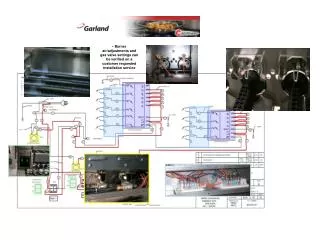
Tracker N2 system From N2 dewar DT1 pressure + flow monitoring (DIP) ECAL ES Parallel dew point meters (interlock) Filters – particulate + oil Extra flow meter on line to TK for interlock
Tracker N2 + air system Can select line for DP monitoring Air / N2 master switch From compressors Pneumatic valves with state transmitters Electro-Pneumatic valves for interlock From bottles Switch-over panel
TK, ECAL + HCAL Small dryer for ECAL / HCAL
Consumption Present consumption 15/04/10 Design Max. flows
Interlocks and Thresholds Requested Interlock Logic. All the hardware to implement it is there. Machi’ s talk for details. Thresholds table
Documentation • The CMS Inertion and Flushing System : Technical Guide • Functionality • Interlocks and monitoring • Failure scenarios and recovery procedures • System maintenance • Contact persons • Filter specifications • Spare parts list • Hyperlinks to Schematics, dryer manuals, pipes distribution, switch over panel pneumatic layout. • Mass flowmeters calibrations • Rotameters calibrations • Instrumentation documentation To be stored in a better place than my hard drive.
Operational model so far…… • No CMS Dry gas system maintenance crew. • Operation and maintenance based on the “good will” system. • Overall Experts: Stefano Moccia, Nick Lumb. • Distribution gas racks experts: PH-DT (Andrea D’ Auria, Roberto Guida, Albin Wasem). • Monitoring: • PH-DT for the distribution racks (pressures and flows to all the subdetectors). Info available via DIP. • TK (flow to the TK volume, valves state, switch over panel, Dew points). • A good number of people in the TK community has helped to run the system. • Occasional interventions for small upgrades, dryer maintenance and tests. • This model has survived so far because the system is quite stable and has not given major problems. • Need to transfer responsibility to PH-DT in order to centralize the operations and maintenance especially if we are going towards colder running conditions for cooling • Need to mesh the two monitoring systems • Need to add some more parmeters to the monitoring (i.e. bottles supply pressure, driers state…..).
Dry Gas system summary • At the present CMS is flushed with N2 (about 62 Nm3/hour) which is the default state for the dry gas system during operations. • The N2 provides the CMS inertion and necessary dryness inside the Vac Tank. • The N2 system has proven to be quite stable and reliable. • The Dry Air system is the backup for N2, but, of course, provides only the dryness. • The only “normal” failure modes for N2 and Dry Air systems are low pressure or high humidity. Tests have proven that the system reacts properly. • Power cuts are taken care (supposedly) by UPS and Diesel. It has never been fully tested. • TC has determined that if there is a switch to Dry Air due to some failure of the N2 system, there is a max waiting time of 1 hour to have the N2 back otherwise the detectors inside the VacTank need to power off. • Better operational model to setup. • Some worries for the Dry Air system as a backup for the N2: • The flushing and the instrument air share the same source (4 compressors for about 139 Nm3/hour). • If there is a switch to Dry Air (N2 problems shutdown configuration with CMS open), with the present consumption, the compressors won’ t be able to keep up with the demand for long. • This could cause a possible failure of the instrument air system causing systems shutdown. • This problem will become more evident in the future when Tracker and Preshower will run at way below subzero temperatures. • Decouple the instrument air from the CMS flushing is recommended along with larger dry air source. • Reduce drastically the consumption for the cooling boxes by improving the sealing, switching to N2…….