Download
1 / 45
450 likes | 860 Views
3- Networks on Chips. سیر تحول تکنولوژی در حوزه ارتباطات روی تراشه. به دلیل افزایش فرکانس و ایجاد تأخیر بیش از حد روی سیم ها، استفاده از باس سراسری برای ارتباط پردازنده ها و واحدهای حافظه در چیپ ها دیگر امکان پذیر نیست.

E N D
سیر تحول تکنولوژی در حوزه ارتباطات روی تراشه • به دلیل افزایش فرکانس و ایجاد تأخیر بیش از حد روی سیم ها، استفاده از باس سراسری برای ارتباط پردازنده ها و واحدهای حافظه در چیپ ها دیگر امکان پذیر نیست. • از سوی دیگر سیستم های روی تراشه از حالت سنتی تک فرکانسی، به سمت مدل جدید GALS(globally asynchronous, locally synchronous)می رود، لذا استفاده از باس سراسری منجر به عبور باس از حوزه های فرکانسی مختلف می شود که امکان پذیر نخواهد بود. • به دلایل فوق سیستم های ارتباطی روی تراشه به سمت شبکه های روی تراشه سوق یافته است.
عدم قطعیت در مدل سازی شبکه روی تراشه • مدلسازی دقیق رفتار سیستم های روی تراشه امروزی با رسم دیاگرام های زمانی به دلیل افزایش پیچیدگی این سیستم ها، دیگر امکان پذیر نیست. • مدل های انتزاعی سطح بالا از اجزاء سیستم های روی تراشه، تبدیل به مدل های غیرقطعی و آماری شده اند. • به دلیل تعدد زیاد المان های متصل به هم در تراشه ها، مدل سازی ترافیک عبوری روی تراشه نیز به طور قطعی امکان پذیر نیست. ترافیک به صورت کاملاً توزیع شده توسط گره ها تولید و مصرف می شود. • لذا برای طراحی شبکه های روی تراشه، از ترکیب مدل های قطعی و آماری استفاده می شود و اهداف طراحی شامل عملکرد و توان مصرفی، باید با استفاده از معیارهای تصادفی مانند میانگین و واریانس، اعلام می شوند. • خوشبختانه مکانیزم طراحی در شبکه ها، به دلیل گستردگی، به صورت سنتی در فضای غیرقطعی و آماری انجام شده است.
رویکرد طراحی جدید در ارتباطات SoC • با توجه به موارد اشاره شده، در طراحی شبکه های روی تراشه می توان از مفاهیم طراحی شبکه های کامپیوتری سنتی و گسترده وام گرفت. • در همین راستا پشته پروتکلی ساده شده زیر برای ریزشبکه های روی تراشه پیشنهاد شده است: • البته باید توجه داشت شبکه های روی تراشه به لحاظ ابعاد و نوع ترافیک عبوری بین گره ها، نسبت به شبکه های گسترده از سادگی و قابلیت پیش بینی بیشتری برخودار هستند. • در نتیجه تنوع و تفکیک وظایف لایه های مختلف در پشته پروتکلی پیشنهادی در مقایسه با شبکه های کامپیوتری ساده تر می باشد.
معماری و کنترل ریزشبکه ها • طراحی شبکه روی تراشه معماری: همبندی و ساختار فیزیکی شبکه پروتکلهای کنترلی: چگونگی استفاده از منابع فیزیکی • به لحاظ معماری، شبکه های روی تراشه بسیار مشابه شبکه های ارتباطی در سیستم های چندپردازنده ای گسترده هستند.
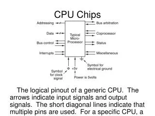
Bus networksشبکه های با محیط اشتراکی • The bus must be used in a time-sharing way. • Typically used for a small (5-10) number of processors. • arbitration strategy: assigns the mastership of the medium and resolves access conflicts. • supports broadcast: advantageous when communication is highly asymmetric. Consumes too much power. • Data., address, and control information can either be time-multiplexed on the bus, or it can travel over dedicated busses.
Bus networksشبکه های با محیط اشتراکی • هماهنگ سازی المانها سنکرون: همه پردازنده های متصل به باس از یک کلاک برای ارسال و دریافت داده استفاده می کنند. فرکانس کلاک باس معمولاً کمتر از کلاک پردازنده هاست. آسنکرون: هر پردازنده با کلاک خودش به باس متصل می شود. در این حالت نیاز به مکانیزم دست دهی بین مبدأ و مقصد داریم. • مکانیزم ارسال پاسخ atomic transaction : پس از ارسال درخواست توسط یک پردازنده، باس قفل می شود تا زمانی که پاسخ آن درخواست روی باس قرار گیرد. split transaction: سرویس دهنده برای ارسال پاسخ باید بر سر کانال رقابت کند.
Bus Architecture IP Block #1 CPU #1 IP Block #2 CPU #2 IP Block #3 IP Block #1 IP Block #4
Bus arbitration Request IP Block #1 CPU #1 IP Block #2 CPU #2 IP Block #3 IP Block #1 IP Block #4
Bus grant Request IP Block #1 Grant CPU #1 IP Block #2 CPU #2 IP Block #3 IP Block #1 IP Block #4
Data transaction Request IP Block #1 Grant CPU #1 Transaction IP Block #2 CPU #2 IP Block #3 IP Block #1 IP Block #4
Bus Arbitration • When multiple masters share a bus there must be some central resource to manage the bus: an arbiter • Once there is competition for the bus, it is possible that it is not ready when you need it: backpressure • Backpressure adds complexity and hurt performance
Pipelined Transactions • To help improve bus efficiency the transactions on the bus can be pipelined • This is really a simple implementation of multiple outstanding transactions • The address for one transaction can be presented before the data from the previous transaction has been completed
Advantages • Relatively easy to add new blocks • Still has the familiar bus structure • Low hardware cost • Bus arbitration “solves” many ordering problems
Disadvantages • Busses that require arbitration: • must route signals to the arbitration logic and back • must find a “fair” way to share the bus • slaves are not always available => backpressure • difficult to provide performance guarantees... • Still potentially a bandwidth bottleneck • Still doesn’t scale well when blocks are added • Multiple outstanding transactions not handled well - no ordering information
Interconnection Networks • Transfer messages from a processor to a destination & back. • The message may contain data, request or control. • The source or destination may be a processor or a memory or I/O module. • Important design criteria of networks: • Topology: describing the interconnection structure • Routing technique: the message transmission path within the network. • They can be described by a connection graph G=(V,E) where V is a set of nodes and E is a set of links between the nodes.
Interconnection Networks Properties • The diameter δ(G) of a network G is the maximum distance between any pair of nodes: • The degree d(G) of a network G is the maximum degree of the nodes of the network. • The degree of a node n is the number of direct neighbor nodes of n. • The bisection bandwidth B(G)of a network G is defined as the minimum number of edges that must be removed to partition the network into two seperated parts of equal size.
Networks Connectivity • The node & edge connectivity of a network measure the number of nodes or edges that must fail to disconnect the network. • The node and edge connectivity of a network is a measure for the number of independent paths between any pair of nodes. • The minimum degree of a node in the network is an upper bound on the edge connectivity. • Network with node connectivity 1, edge connectivity 2, and degree 4. The smallest degree of a node is 3.
Desirable Topological Properties for Networks in Parallel systems • small diameter to ensure small distances for message transmission, • small node degree to reduce the hardware overhead for the nodes, • large bisection bandwidth to obtain large data throughputs, • large connectivity to ensure reliability of the network, • embedding into a large number of networks to ensure flexibility, • easy extendibility to a larger number of nodes.
Direct Interconnection Networks Intel Teraflop IBM BlueGene
Direct Interconnection Networks Cube Connected Cycles
Direct Interconnection Networks k-dimensional shuffle-exchange network • α and β differ in the last bit (exchange edge) or • α results from β by a cyclic left shift or a cyclic right shift (shuffle edge).
k-ary d-cube Network • A k-ary 1-cube is a ring with k nodes, • a k-ary 2-cube is a torus with k^2 nodes, • a 3-ary 3-cube is a three-dimensional torus with 3 × 3 × 3 nodes, • k ≥ 2 is a generalization of the d-dimensional cube with n = k^d • a 2-ary d-cube is a d-dimensional cube.
Indirect Interconnection Networks • switches are used and provide an indirect connection between the nodes. • Topological structures: • multistage networks • crossbar networks
Crossbar networks • An n ×m crossbar has n inputs and m outputs. • The network consists of n ・ m switches. • Crossbar networks are used for a small number of processors because of the large hardware overhead.
Multistage switching networks • consist of several stages of switches with connecting wires between neighboring stages. • Popular multistage networks are: omega, baseline, butterfly, Beneš, and fat-tree networks.
Omega network • An n × n omega network is composed of log n stages such that each stage contains n (2*2) switches. • There is an edge from node (α, i ) in stage i to node (β, i + 1) in stage i + 1, where β is defined as follows: 1. β results from α by a cyclic left shift, or 2. β results from α by a cyclic left shift and inversion of the last bit.
Butterfly network • An n × n butterfly network is composed of log n stages such that each stage contains n (2*2) switches. • There is an edge from node (α, i ) in stage i to node (β, i + 1) in stage i + 1, where β is defined as follows: 1. β and α are identical (straight edge), or 2. β and α differ in precisely the(i + 1)th bit from the left (cross edge).
Baseline network • An n × n baseline network is composed of log n stages such that each stage contains n (2*2) switches. There is an edge from node (α, i ) in stage i to node (β, i + 1) in stage i + 1, where β is defined as follows: (n=2^(k+1)) 1. β results from α by a cyclic right shift on the last k − i bits of α, or 2. β results from α by first inverting the last bit of α and then performing a cyclic right shift on the last k − i bits.
Beneš network • The k-dimensional Beneš network is constructed from two (forward and backward) k-dimensional butterfly networks. The last stage (k + 1) of the first butterfly network and the first stage of the second (reverted) network are merged. In total, the k-dimensional Beneš network has 2k + 1 stages with 2k switches in each stage.
Fat tree network • each level i of the tree from leaf upward, consists of n switches in total, grouped in 2^(log(n)−i) nodes.
الگوریتم های سوییچینگ: 1- سوییچینگ مداری • در روش سوییچینگ مداری، تمام یا بخشی از ظرفیت پورتها در مسیریاب های میانی در فاز تشکیل مسیر رزرو می شود. سپس بسته ها از مبدأ به مقصد روی مسیر رزرو شده انتقال می یابند. در عبور بسته انتهایی مسیر رزرو شده آزاد می شود. • مزایا: • مناسب برای ترافیک های دائم و طولانی • قابلیت تضمین پهنای باند و تأخیر • معایب: • تأخیر راه اندازی و آزاد سازی مسیر • عدم استفاده بهینه از منابع شبکه به دلیل رزرو شدن
الگوریتم های سوییچینگ: 2- سوییچینگ بسته ای • در روش سوییچینگ بسته ای، هر بسته به طور مستقل و کامل در هر گره میانی دریافت و پس از تصمیم گیری در خصوص پورت خروجی، به سمت گره بعدی ارسال می گردد. • این مکانیزم به ذخیره-هدایت (store and forward) نیز شهرت دارد. • مزایا: • استفاده مناسب تر از منابع شبکه • معایب: • تأخیر زیاد به دلیل لزوم بافر کردن کل بسته در گره پیش از ارسال • امکان دریافت بسته ها به صورت خارج از نوبت در گره انتهایی
الگوریتم های سوییچینگ: 3- سوییچینگ برشی • در روش سوییچینگ برشی (cut-through)، برای کاهش میزان بافر مورد نیاز و تأخیر ناشی از بافر کردن کل بسته، هر بسته می تواند پیش از آنکه به طور کامل در پورت ورودی دریافت شود، پس از تعیین مسیر به سمت پورت خروجی مناسب ارسال گردد. • مزایا: • استفاده مناسب تر از بافرها و افزایش سرعت ارسال شبکه • معایب: • در شرایط پر ترافیک احتمال بلاک شدن برخی درگاه ها و اتصال ها وجود دارد چون یک بسته ممکن است به طور همزمان چندین درگاه و اتصال را اشغال نماید.
الگوریتم های سوییچینگ: 4- سوییچینگ گرمچاله • در روش سوییچینگ کرمچاله (wormhole)، فلیت سرآیند در حین عبور از هر سوییچ منابع لازم به اضافه میزان بافری معادل یک فلیت را روی آن برای عبور فلیت های بعدی رزرو می کند. آخرین فلیت از بسته، منابع و مسیر سوییچینگ رزرو شده را آزاد می کند. • مزایا: • استفاده مناسب تر از بافرها (تنها نیاز به بافر معادل یک فلیت برای هر اتصال) • دارای مزایای هر سه روش سوییچینگ قبلی • به عنوان روش سوییچینگ متداول در شبکه های روی تراشه فعلی استفاده می شود.
مثال های پیاده سازی 1- در معماری SPIN از مسیریابی کرمچاله ای و همبندی درخت فربه برای اتصال گره ها استفاده شده است. 2- در معماری Aethereal از دو مود برای هدایت بسته ها استفاده می شود: - بهترین تلاش: از سوییچنگ کرمچاله استفاده می شود. - تضمین شده: از سوییچنگ مداری با روش دسترسی TDM استفاده می شود.
Routing Algorithms • The following issues are important for the path selection: • network topology: determines which paths are available between nodes A and B; • network contention: when multiple messages should be transmitted at the same time over the same link; • network congestion: when too many messages are assigned to a network link or buffer such that arriving messages have to be discarded.
Dimension-order routing 1- XY routing for two-dimensional meshes: To send a message from node A withposition (XA, YA) to node B with position (XB, YB), it is sent from the source node into X-direction until XB is reached. Then, it is sent into Y-direction until YB is reached. The length of the path is | XA − XB | + | YA −YB |. This routing algorithm is deterministic and minimal.
Dimension-order routing 2-E-cube routing for hypercubes: • Let α = α0 . . . αk−1 be the bit representation of A and β = β0 . . . βk−1 be the bit representation of B; • Let Ai with bit representation γ = γ0 . . . γk−1 be a node on the routing path; • For the forwarding from Ai to Ai+1, the following two substeps are made: • The bit string γ ⊕ β is computed. • The message is forwarded in dimension d (the rightmost bit position of γ ⊕β with value 1). The next node Ai+1 on the routing path is obtained by inverting the dthbit in γ. The target node B is reached when γ ⊕ β = 0.
Routing in the Omega Network • To forward a message from an input channel with bit representation α to an output channel with bit representation β the receiving switch on stage k of the network, considersβk(from the left) and selects the output link according to the following rule: • for βk = 0, the message is forwarded over the upper link • for βk = 1, the message is forwarded over the lower link Source destination