Download
1 / 25
250 likes | 339 Views
The Path to Accelerator Commissioning. F. Willeke Accelerator Systems Director NSLS-II PAC Meeting December 10-11, 2009. Start-Up and Test Plan. framework of documents: clearly identifies requirements for documentation readiness, technical readiness,

E N D
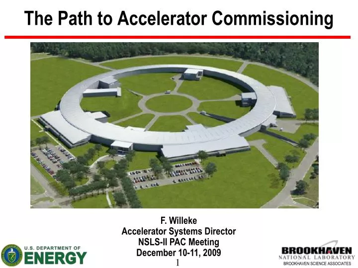
The Path to Accelerator Commissioning F. Willeke Accelerator Systems Director NSLS-II PAC Meeting December 10-11, 2009
Start-Up and Test Plan • framework of documents: clearly identifies requirements for • documentation readiness, • technical readiness, • personnel Training and Qualification, • hardware and software testing • defines the acceptance criteria for CD-4 at the end of commissioning. • hardware and software testing: • sub-system testing and qualification, • integrated system tests • commissioning with beam • • this document is necessary at this stage to start preparing for start-up
Integrated Testing • Integrated Testing Technical test of Accelerator Subsystems • - Check out Safety Systems (this is not the “official” safety test) • Prepare systems for operations • Test automatic and semi-automatic turn-o procedures • - Verify Assignment, Polarization, Correct Magnitude • Examples: • Systematic check of the components of the safety systems (door locks, shutter positions, including correct wiring, interfaces to RF, main dipole Power Supply, injection/extraction pulsed magnets • Check Assignment, polarity and magnitude of the magnet current s in the accelerator tunnel as directed by setting using the application • Check assignments of thermal protection switches on magnets to PS via application software • Test of the vacuum system, fine-leak checking and fixing, in-situ bake-out • Turn on/off all power supplies by automatic procedures
Safety System Verification • Formal technical check, Well documented process • Performed by an independent group (Laboratory QA and Light Source ES&H personal • Governed by Laboratory Standards and by DOE requirements • Technical checks out include (but are not limited to) • functioning of components • - door contacts, door-warning lights • - emergency buttons, • - mechanical systems: fences, • - warning signs, signs indicating emergency buttons • - warning systems: acoustical warning, blink-lights, tunnel lightening, warning-tableaus • - Interfaces to accelerator hardware: RF, main dipole, shutters, triggers for septa, gun, • Interlock logics: check whether any kind of anomalous status will lead to desired effect (turn-off the beam, RF ) • training of operators and key personal
Requirements Radiation Safety Systems Testing • BNL DOCUMENTS DEFINING THE REQUIREMENTS • accelerator readiness review that must be conducted prior to a commissioning • “Template for the Accelerator Readiness Review (ARR) Plan of Action” • BNL interlock requirements that apply: • “Physical Access Controls for High and Very High Radiation Areas” • Effective Date: Jan 8, 2004 (Reviewed: Jan 8, 2004) | Periodic Review Due: Dec 31, 2009 • the interlock test program at the NSLS • http://www.nsls.bnl.gov/esh/qa/pps.htm
Start-Up and Test Plan • framework of documents: clearly identifies requirements for • documentation readiness, • technical readiness, • personnel training and qualification, • hardware and software testing • defines the acceptance criteria for CD-4 at the end of commissioning. • hardware and software testing: • sub-system testing and qualification, • integrated system tests, • commissioning with beam
Commissioning • particular mode of accelerator operation with beam aiming: • test the function of accelerator hardware and software with beam, • verify in particular the proper functioning of the equipment protection system, • verify the adequacy of radiation safety shielding, area radiation monitoring, ALARA system to minimize radiation • check the integrity and the consistency of the subsystems as built • develop refined settings of the hardware components to allow efficient injection, and storage of accelerator beams with good stability, beam intensity, the advertised beam parameters, and good beam lifetime. • condition accelerator hardware for optimum performance (vacuum, RF) • develop and document the procedures which are necessary to operate the accelerator routinely and to perform continuous improvement and development.
Commissioning Authorization • Commissioning needs BHSO approval • authorization process, addressing all relevant issues • completeness of documentation, • technical readiness, • training of the staff, • existence of detailed commission procedures, • assessment of hazards, • safety and emergency procedures.
Guiding Documents • The NSLS-II Authorization Base is defined by the requirements and the guidance in: • DOE Order 420.2B “Safety of Accelerator Facilities” • DOE Guide 420.2-1 “Accelerator Facility Safety Implementation Guide” • DOE Order 413.3B “Program and Project Management for the Acquisition of Capital Assets” • BNL SBMS Subject Area “Accelerator Safety”
Elements of the Authorization Base • Commissioning Modules • LINAC (including LINAC to Booster Transfer Line) • Booster (including Booster to Storage Ring Transfer Line) • Storage Ring • Full Operations (roll-up of first three modules) • Module Components (concluded by authorizations and reviews) • SAD (Safety Assessment Document) • ASE (Accelerator Safety Envelope) • Authorization Plan (commissioning plan) • ORE (Occupational Readiness Evaluation) • ARR (Accelerator Readiness Review)
Coupling of Schedule Elements Includes staff training
Commissioning Stages LINAC Frontend (gun pre-buncher) early delivery, commissioning and early tests by NSLS-II staff in RF Lab, Special bunch-modes LINAC commissioning by the vendor (responsible) LtBTL (LINAC building part ) commissioned by NSLS-II-Staff , primary + secondary beam dump Booster LBTL commissioning by NSLS-II staff in parallel to booster integrated testing Booster commissioning by vendor (vendor’s responsibility), participation of NSLS-II staff BSTL (part in booster tunnel) performed by NSLS-II staff with project responsibility Storage Ring Commissioning Phase 1 (without ID) BSTL commissioning and injection set up ; the storage ring beam optics; adequacy of correction systems; adequacy of safety and ALARA systems; efficient injection; adequacy of beam instrumentation; orbital stability; RF set up and stability; RF conditioning; cryogenic stability; beam stability; vacuum integrity and conditioning; high intensity operations Storage Ring Commissioning Phase 2 Integrate Insertion devices
Assumptions on Conditions • accelerator tunnel air conditioned; tunnel temperature, humidity within specified range. • final survey and alignment shortly before start commissioning (ground settling) • heavy duty construction activities completed • global utilities available: electrical, de-ionized water, chilled water, and liquid N2 • CF deliverables • installation of girders and magnets completed ~1/2 year start of commissioning. • cable conduits and openings in the tunnel walls will be properly closed and shielded
SR Subsystem Status at Commissioning • integrated testing complete • Injectors and transfer lines commissioned • personal safety system and interfaces thoroughly tested • equipment protection system is fully implemented and tested via the control system. • magnets systems installed well before commissioning, • precision alignment shortly before commissioning • insertion devices will not be installed • power supply systems are complete, technical interlocks have been properly tested • vacuum system has a vacuum of at least 10-7 mbar • two sc RF cavities installed driven by a single 310kW transmitter station. • full suite of beam diagnostics is installed and tested • water cooling systems have been installed tested • timing system implemented • control system is fully implemented • relational database is fully functional • all application programs deemed necessary for commissioning available • injection systems have been installed and tested • fast orbit feedback has been implemented • transverse feedback damper system installed and tested
Radiation Safety during Commissioning • radiation protection systems installed and fully tested, no provisory solutions allowed, no exception possible. • initial beam intensity very small compared to nominal (0.1%). • area monitors readings low intensity will be extrapolated to the next step in beam intensity. • extrapolation is reviewed and analyzed at each level of intensity before the next step in intensity is made. • initial high intensity studies: assume losses e much larger than under optimized normal conditions may need special (temporary controlled radiation areas) • beam containment system needs to be tested with beam, location of beam losses identified, beam is lost dominantly in the extra shielded confirmed • clear and unambiguous procedures operating staff needs to be trained to follow these procedures before operations with continuous injection of high charge (top-off, high intensity operation) can proceed.
Storage Ring Commissioning Modules COMMSIONING PART I Establish Initial Beam Operation, 5 moduls Check out Beam Instrumentation 4 moduls Check out Safety Functions 3modules Fine tuning of Beam Optics 7modules Functionality Tests 1moduls Fine Tuning of Orbit and Emittance 3modules Synchrotron Radiation Measurements 4mod. High Intensity Studies 10 modules COMMSIONING PART II Safety Related Measurements 2 modules ID Integration 8 x 7 modules Preparation of User Operation 3 modules 70 commissioning modules Each needs ~4 shifts on average ~300 shifts 100 days Operational efficiency is assumed 50% Need 200 days of commissioning
Storage Ring Commissioning Part I Establish Initial Beam Operation Obtain stored beam Adjust and verify RF parameters first Orbit Correction first iteration of correcting chromaticity and coupling first iteration of obtaining acceptable injection efficiency Check out Beam Instrumentation establish beam monitor calibration with local bumps checking intensity monitors checking out loss monitors checking out emittance monitors Check out Safety Functions Checkout top-off safety functions Check-out machine protection system Check out BCS and ALARA functionality Fine tuning of Beam Optics Beam Optics Checks and correction (Response matrix, phase advance, coupling measurements) Beam based alignment measurement of chromatic distortions and correction nonlinear dynamics related measurements and corrections (D.A., amplitude dependent tune shift, width of resonances, higher order chromaticity) measure 1st and 2nd order momentum compaction factor measure damping distribution Functionality Tests Fast orbit feed-back test Fine Tuning of Orbit and Emittance Orbit correction to micron level dispersion free steering and orbit correction vertical emittance tuning Synchrotron Radiation Measurements Measurement of power deposition s and power load check of temperature monitor system check of vacuum interlock check of assumptions on absorber and mask temperatures, monitoring and cooling High Intensity Studies Set up of high efficient injection Set-up of RF feedback and fine tuning of feedback parameters and LLRF Single Bunch Intensity Limit measurements bunch lengthening by 3rd harmonic cavity beam lifetime vs bunch length and bunch intensity study BCS and ALARA studies with high intensity Vacuum conditioning beam RF conditioning with beam transverse damper test Study of high multi-bunch intensity limitations
Commissioning Staffing • commissioning will be organized in 3 8hr shifts per day and seven days per week. • commissioning labor budgeted within the project • commissioning requires operation of already commissioned subsystem • (injectors, cryogenics, utilities) • commissioning requires the involvement of all accelerator physicists (budgeted) , • subsystem experts (budgeted) and operators • workload of off-hour shifts will be shared between all high level staff • engineers and technicians on call during commissioning • control room manned with 1 accelerator physicist ~33 weeks. @ 16000 hr (budgeted) • involvement of engineers less regular, will depend on the commissioning program • initially, one machine operator present every shift • will gradually develop into a mode with 2 operators and no accelerator physicists.
Commissioning Information and Documentation • semi-formal meetings of 15 min at shift change ( coming and going shift crews) • seamless transition from one shift to the next, communicate and discuss fine-tuning of program. • 3 shifts per day and thus there will be three such meetings. • weekly commissioning meeting will summarize the commissioning results. • opportunity to optimize the commissioning program and direction. • weekly commissioning meetings will be documented including all material presented. • commissioning carried out in modules (ca 200) each requires written plan: • the purpose, • the goal, • supporting documents, • results of calculations necessary to carry out the module • estimate on the needed machine time • labor resources required. • results of each module will be documented • raw data will be stored in an organized and accessible way • evaluation, resulting set-points, procedures, parameters will be documented • commissioning report will be published at the end of commissioning
Applications needed for Commissioning Major Subsystem Control Power supply page RF monitor and control Vacuum display and control Cryogenics system display and control pulsed magnet monitor and control injection element display and control Insertion device control Front-end control and status Beam Diagnostics Beam Orbit page with Beam current history and lifetime bunch intensity display and history beam emittance display Timing system display and control Synchronization system displ & contr Tune display and control Temperature monitoring display Safety Systems personal protection system status equipment protection display and control beam containment display and control top-off status monitor • Utility Control • tunnel temperature and humidity monitor • mechanical utilities status and control • electrical utilities status and controls • equipment enclosure monitor • water cooling system display • controls network monitor • Accelerator physics applications • static orbit corrections, first turn steering, • chromatic correction, • response matrix measurements, • phase advance measurements, • beam base alignment measurement, • bpm test programs, • beam optics measurement, • beam based alignment of sextupoles, • analysis on nonlinearities • dispersion measurement and correction, • closed Orbit bump page Operation Software overall status page status, alarm and warning monitor permit system monitor and control data logger and data display electronic logbook Operations Software accelerator store/restore Injection Control power supply control RF control fast orbit feedback control fast transverse damper control front-end monitoring and control machine protection displ &contr magnet temp. interlock dspl & contr scraper and collimators system turn-on, system shutdown
Accelerator Control Room during Commissioning • accelerator control room is the location where: • operators operate the accelerator • operators coordinate with technical staff about technical difficulties and interventions • accelerator experiment are carried out • a logbook on accelerator operations is kept and maintained, • information in case of an emergency is to be obtained and such information will be delivered to • an access point is established which manned 24hr a day 7 days a week • day-to-day coordination between accelerator and experimental floor are exchanged, • shift-change briefing meetings are held, • first hand information on the status of the accelerator is available • the responsibility for operating the accelerator safely within the safety regulations resides • routine safety measures are coordinated (LOTO) • preparation of the accelerator for operations is coordinated after an interruption • computer provide an optimized selection of delays for quick overview of accelerator status • an emergency stop button and other special installation (LAN, site-wide audio) are installed • functionality very different between commissioning and operation • at commissioning assumed that the control room is close to the accelerator hardware • control room LAN is accessible from the accelerator tunnel and from the mezzanine.
Summary We have defined a clear path to commissioning The associated formal procedures and the regulatory has been taken into account in the planning There is good understanding of the circumstances under which commissioning will take place There is a good understanding what needs to be done which is base of the preliminary plan Commissioning budget and schedule are in place (need to revisit once the plan has matured Next goal is to present a “Start up and Commissioning Plan” to be presented at the Lehman review in February