Download
1 / 13
130 likes | 312 Views
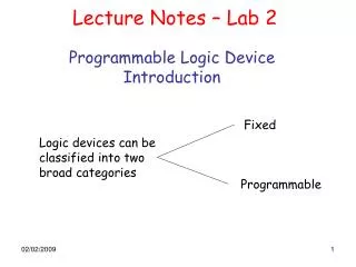
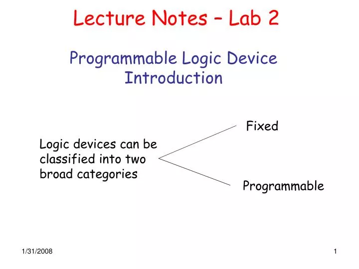
Lecture Notes – Lab 2. Programmable Logic Device Introduction. Fixed. Logic devices can be classified into two broad categories. Programmable.

E N D
Lecture Notes – Lab 2 Programmable Logic DeviceIntroduction Fixed Logic devices can be classified into two broad categories Programmable
Small-Scale Integration (SSI) uses circuits containing transistors numbering in the tens, while Medium-Scale Integration" (MSI) contains hundreds of transistors on each chip. Fixed Logic Devices (e.g. SSI/MSI) Disadvantages • Circuits are permanent • They perform one function or set of functions • Once manufactured, they cannot be changed • Constrained to parts • Need to stock many different parts • Most resources (power, board area, manufacturing cost) are consumed by the “package” but not by the “silicon”, which performs the actual computation. • Automation is impossible Example
Lecture Notes – Lab 2 Programmable Logic Devices • Devices can be changed at any time to perform any number of functions. • Use a single chip (or a small number of chips). • Program it for the circuit you want. • Testing using simulation. • Then, a design can be quickly programmed into a device, and immediately tested in a live circuit. Example: Field programmable gate array (FPGA) A gate-array-like architecture with a matrix of logic cells surrounded by a periphery of I/O cells where the interconnect mask is defined after the IC has been manufactured.
Lecture Notes – Lab 2 FPGA. Basic idea: two-dimensional array of configurable logic blocks (CLBs) that can implement combinational or sequential logic FPGAs provides a method to configure (program): 1. The interconnection between CLBs. 2. The function of each CLB. Simplified version of FPGA internal architecture
Lecture Notes – Lab 2 FPGA Generic Design Flow Design Entry Design Verification • Design Entry: • Create your design files using: • schematic editor or • hardware description language (e.g., VHDL) • Design “implementation” on FPGA: • Partition, place, route, … • Design verification: • Use Simulator to check function, • Load onto FPGA device (cable connects PC to development board) • check operation at full speed in real environment. Design Implementation
Lecture Notes – Lab 2 Programming Language Can we use a traditional programming language (e.g., C or Java) as a Hardware description language (HDL)? Traditional PL • Useful to model sequential processes – Operations performed in a sequential order – Help human's thinking process to develop an algorithm step by step – Resemble the operation of a basic computer model
Lecture Notes – Lab 2 Event a a sum b b carry sum carry 30 5 10 15 20 25 35 40 T i me (ns) Digital systems Digital systems are about signals and their values Events, propagation delays, concurrency. Signal value changes at specific points in time. Time ordered sequence of events produces a waveform These characteristics are hard to be captured by traditional PLs
Lecture Notes – Lab 2 VHDL - Very High Speed Integrated Circuit Hardware Description Language Key Point: You can use the software to describe the behavior of the circuit you wish to develop and then implement the design on programmable logic devices.
sum a b carry Describing the Interface: The Entity Construct case insensitive • The interface is a collection of ports • Ports are a new programming object: signal • Ports have a type, e.g.,bit • Ports have a mode: in, out, inout (bidirectional) entity half_ADder is port ( a, b : inbit; sum, carry :outbit); end entity half_adder; VHDL 1993
The Signal Object Type • VHDL supports four basic objects: variables, constants, signals and file types (1993) • Variable and constant types • Follow traditional concepts • The signal object type is motivated by digital system modeling • Distinct from variable types in the association of time with values • Implementation of a signal is a sequence of time-value pairs! • Analogous to wires used to connect components of a digital circuit Signal declarationSignal signal_name: signal_type := initial_value SIGNAL sig1: STD_LOGIC; SIGNAL sig1: STD_LOGIC := ‘1’; SIGNAL sig1(1 DOWNTO0): STD_LOGIC_VECTOR := “10”;
sum a b carry Describing Behavior: The Architecture Construct entity half_adder is port (a, b : inbit; sum, carry :outbit); end entity half_adder; architecture behavioral of half_adder is begin sum <= (a xor b) after 5 ns; carry <= (a and b) after 5 ns; end architecture behavior; • Description of events on output signals in terms of events on input signals: the signal assignment statement • Specification of propagation delays VHDL 1993
Lecture Notes – Lab 2 Basic VHDL building blocks Example 1: Consider the following circuit: Entity sig1 Architecture ENTITY fewgates IS PORT ( A : IN STD_LOGIC; B : IN STD_LOGIC; C : IN STD_LOGIC; Y : OUT STD_LOGIC ); END fewgates; ARCHITECTURE c1_behavior OF fewgates IS SIGNAL sig1: STD_LOGIC; BEGIN sig1<=(NOT A) AND (NOT B); Y <= C OR sig1; END c1_behavior;
Signal Assignment • The constant programming object • Values cannot be changed • Use of signals in the architecture • Internal signals connect components • A statement is executed when an event takes place on a signal in the RHS of an expression • 1-1 correspondence between signal assignment statements and signals in the circuit • Order of statement execution follows propagation of events in the circuit • Textual order does not imply execution order