Download
1 / 30
370 likes | 709 Views
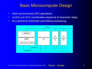
Lecture 01: Introduction to Microcomputer & Embedded Systems. What is a computer?. Von Neumann Architecture. I/O devices. 1.Five components partitioning Input Output Memory ALU Control unit 2. Three key concepts:

E N D
Lecture 01: Introduction to Microcomputer & Embedded Systems
Von Neumann Architecture I/O devices 1.Five components partitioning • Input • Output • Memory • ALU • Control unit 2. Three key concepts: • Both instructions and data are stored in a single read-write memory • The contents of memory are addressable by location, without regard to the type of data • Execution occurs in a sequential fashion Memory CPU Harvard architecture
Microprocessor • Microprocessors • the CPU circuitry can been reduced to IC (Integrated Circuit) scale, consisting of ALU, CU and registers • contains no RAM, ROM, or I/O ports on the chip itself • e.g., Intel’s x86 family (8088, 8086, 80386, 80386, 80486, Pentium); Motorola’s 680x0 family (68000, 68010, 68020, etc)
Microcomputer • CPU: processes information stored in the memory • Microprocessor • Memory: stores both instructions and data • ROM, RAM • Input/Output ports: provide a means of communicating with the CPU • Connecting I/O devices, e.g., keyboard, monitor, tape, disk, printer and etc. • BUS: interconnecting all parts together • Address bus • Data bus • Control bus
Microcomputer Structure Address bus I/O ports I/O devices Memory CPU Data bus Control bus
Microcomputer System • Microcomputer • Peripheral I/O devices • Software • System software • e.g., OS, compilers, drivers • Application software • e.g. Word, QQ, Media player, …
Hardware: CPU (1) - ALU Input Input • Arithmetic Logic Unit (ALU) • Arithmetic functions: add, subtract, multiply and divide • Logic functions: AND, OR, and NOT • ALU is a multifunctional calculator • What specific calculation will be taken depends on the particular control signal • Two inputs • Calculation result can be temporarily stored in one of the registers control signal ALU results
Hardware: CPU (2) - CU • Control Unit works under instructions • An instruction is a pre-defined code which defines a specific operation, processing and exchanging information among CPU, memory and I/O devices. • CU contains an instructor decoder • decodes an instruction and generates all control signals, coordinating all activities within the computer • CU contains a program counter • points to the address of the next instruction to be executed
Hardware: CPU (3) – Instruction Set • The instruction set • All recognizable instructions by the instruction decoder • CISC (Complex Instruction Set Computers) • Variable instruction length (1 word- n words) • Variable execution time of different format instruction • More instruction formats • Upwardly compatible (new instruction set contains earlier generation’s instructions) • e.g., 80x86 family has more than 3000 instructions • RISC (Reduced Instruction Set Computers) • Fixed size of RISC instruction (1 word) • Fixed time for all instructions • Easy to pipeline the RISC instructions (fast) • Fewer formats (simple hardware, shorter design cycle) • e.g., PowerPC, MIPS, ARM, PIC’s MCU
Hardware: Memory • Memory hierarchy • Cache • Primary memory: ROM, RAM • Secondary memory: magnetic disk, optical memory, tape, …
Hardware: Memory • Bit (b): a binary digit that can have the value 0 or 1 • Byte (B): consists of 8 bits • smallest unit that can be addressed in microcomputers • Nibble: is half a byte (4bits) • Word: the number of bits that a CPU can process at one time • depends on the width of the CPU’s registers and that of the data bus • e.g., if the width of the data bus is 16 bits, then a word is 16 bits; if the width of the data bus is 32 bits, then a word is 32 bits • Double word • Kilo, Mega, Giga, Tera, Peta, … 10101010
Memory Module Organization • To organize a memory module: • If the module needs bigger unit of transfer than that of given memory chips, bit extension • If the module needs larger number of words than that of given memory chips, word extension • 8-bit • 16-bit • 32-bit
Hardware: Bus • A bus is a communication pathway connecting two or more devices • A shared transmission medium: one device at a time • System bus: connects major computer components (processor, memory, I/O) • Devices connected into a bus: • Sending/receiving • Master/Slave • Master activates a bus • Slave passively waits for command
Hardware: Bus • Type • Dedicated (e.g., physical dedication)/Multiplexed (e.g., time multiplexing) • Arbitration • Centralized: bus controller responsible for allocating time on a bus • Distributed: each module has access control logic and collaborate • Timing • Synchronous: events on the bus is determined by a clock, a single 1-0 transmission is referred to as a bus cycle • Asynchronous: master and slave devices communicates before and after an event, e.g., master/slave sync
Single-bus Structure AB A bus connects all modules • pro:simple • con:poor performance in terms of throughput IOdevice CPU RAM ROM I/Oports IOdevice DB CB
CPU-Central Dual-Bus Structure • A dedicated bus between CPU and memory, and a dedicated bus between CPU and I/O devices • pro:efficient in terms of data transfer • con:information between memory and I/O devices has to go through CPU. Therefore, poor CPU performance I/O bus CPU I/O ports I/O ports I/O ports Memory bus Memory IOdevice IOdevice IOdevice
Memory-Central Dual-Bus Structure I/Obus • Gain both High CPU performance and data transfer throughput Memory I/Oport I/O port CPU Memory bus IOdevice IOdevice
Hardware: BUS (1) – Data Bus • Used to provide a path for moving data between system modules • Bidirectional • CPU read: Memory (I/O device) -> CPU • CPU write: CPU -> Memory (I/O device) • The width of data bus • is as wide as the registers of a CPU (i.e. the width of a word) • determines how much data the processor can read or write in one memory or I/O cycle
Hardware: BUS (2) - Address Bus • Used to designate the source or destination of the data on the data bus that the processor intends to communicate with • Unidirectional • CPU -> memory| I/O device • The width of the address bus, n • determines the total number of memory locations addressable by a given CPU, which is 2n • e.g., 8086 has a 20-bit address bus which corresponds to 220 addresses or 1M (1 Meg) addresses or memory locations; • Pentium has 32-bit address bus, what is the size of its addressable memory?
Hardware: BUS (3) – Control Bus • Used to control the access to and the use of data and address buses • Command and timing information between modules • e.g., memory read/write, IO read/write, Bus request/grant • Consists of two sets of unidirectional control signals • Command signal: CPU -> Memory (I/O device) • State signal: Memory (I/O device) -> CPU • Input/Output is defined from the processor’s point of view • e.g., when Memory (I/O device) Read is active, data is input to the processor
Hardware: I/O Modules Addressing scheme to accessing memory and I/O modules • Memory-mapped I/O • One single address space for both memory and I/O • Status and data registers of I/O modules are treated as memory locations • Using the same machine instructions to access both • Isolated I/O • Two separate address spaces for memory and I/O modules • Using different sets of accessing instructions
Isolated I/O Dedicated address lines Multiplexing address lines
Microcontrollers (MCS) A microcontroller has a CPU in addition to a fixed amount of RAM, ROM, I/O ports on one single chip • Ideal for applications in which cost and space are critical • Example: a TV remote control does not need the computing power of a 486
Embedded Systems • An embedded system uses a microcontroller or a microprocessor to do one task and one task only • Example: toys, TV remote, keyless entry, etc. • Using microcontrollers is cheap but sometimes inadequate for the task • Microcontrollers differ in terms of their RAM,ROM, I/O sizes and type. • ROM (often used as program memory, like BIOS) • OTP (One Time-Programmable) • UV-ROM, EEPROM • Flash memory • RAM (can be used as both program mem and data mem) • SRAM(static RAM):cache • DRAM(Dynamic RAM): main memory • SDRAM (Synchrous DRAM) • DDR DRAM (Double Data Rate DRAM) • DDRII