Download
1 / 25
250 likes | 381 Views
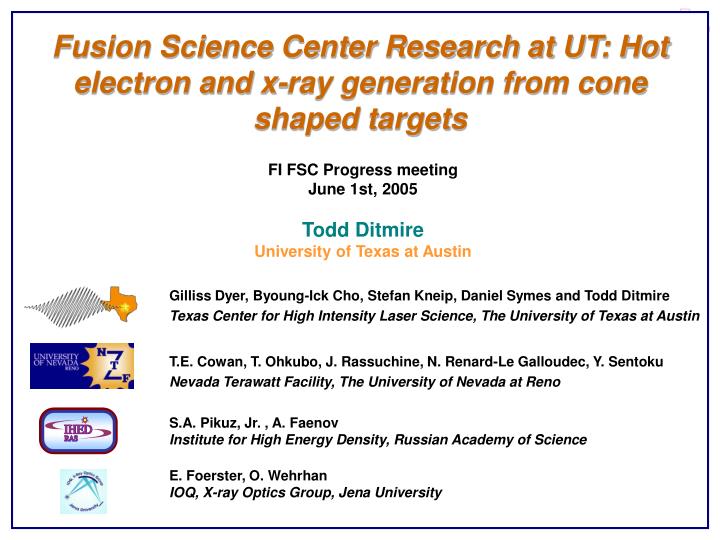
Fusion Science Center Research at UT: Hot electron and x-ray generation from cone shaped targets. FI FSC Progress meeting June 1st, 2005 Todd Ditmire University of Texas at Austin. Gilliss Dyer, Byoung-Ick Cho, Ste f an Kneip, Daniel Symes and Todd Ditmire

E N D
Fusion Science Center Research at UT: Hot electron and x-ray generation from cone shaped targets FI FSC Progress meeting June 1st, 2005 Todd Ditmire University of Texas at Austin Gilliss Dyer, Byoung-Ick Cho, Stefan Kneip, Daniel Symes and Todd Ditmire Texas Center for High Intensity Laser Science, The University of Texas at Austin T.E. Cowan, T. Ohkubo, J. Rassuchine, N. Renard-Le Galloudec, Y. Sentoku Nevada Terawatt Facility, The University of Nevada at Reno S.A. Pikuz, Jr. , A. Faenov Institute for High Energy Density, Russian Academy of Science E. Foerster, O. Wehrhan IOQ, X-ray Optics Group, Jena University
Many hot electronsHigh energy conversion efficiency Small Kα spot Bright Kα Emission Tip size < 5mm Laser Spot ~ 20mm Opening angle < 90° Our contribution to the FI FSC is in the study of hot electron generation in cone targets The spot from which x-rays originate is found to be considerably larger than the laser spot Proposed approach: Study x-ray source size and brightness from cone targets in silicon with x-ray converter layers
z y polarization B x Contour of Bz/B0 y 3D structure of the magnetic field x Based on modeling at UNR, we have begun a study of hot electron generation in cone targets Incident & reflective electric fields Surface current Magnetic field Push electrons out to the interior of the cone p-pol Magnetic field (Bz) Y. Sentoku, et al., Laser Light and Hot Electron Micro Focusing using a Conical Target; Phys. Plas, 11, 3083 (2004)
z y polarization B E x Bz & Ey y Electron angular distribution in p-space x Simualtions indicate that electrons are accelerated along the cone surface toward the tip of the cone Electrons are driven back by the sheath field Forces are balanced Electrons are trapped on the surface Electron flow Sheath field (En) Magnetic field (Bz) Y. Sentoku, et al., Laser Light and Hot Electron Micro Focusing using a Conical Target; Phys. Plas, 11, 3083 (2004)
Contour of EM Energy Electron energy density Electron temperature @ tip Hot electrons and laser light are guided inside the conical target and focused at the tip A portion of the energy in the tip region is higher than that in the same region of a flat target The conical target appears to increase the number of electrons accelerated forward by more than one order of magnitude Y. Sentoku, et al., Laser Light and Hot Electron Micro Focusing using a Conical Target; Phys. Plas, 11, 3083 (2004)
Surface Orientation <100> <111> Surface Orientation <110> 54.74º <111> We use the fact that the KOH etching rates in Si are strongly affected by the crystallographic orientation Anisotropic KOH Etching Rates vs. Orientation (111) the Close- Packed Surface Diamond Structure of Silicon Double FCC Slow Chemical Reaction @ 70ºC, 30% KOH
30% KOH solution is used to etch the Si 100 plane at a 1mm/min etching rate The tip of pyramid goes to the reverse side as close as possible Si2N3 Deposition Furnace @ 950ºC Immerse in KOH solution Optical Lithography PR coat, UV, Develop Reactive Ion Etching Vacuum @ 10-5 torr KOH etching done KOH Etching ~ 7 hours @ 60ºC Metal Layer Coating Low Z material (Ti, Cu)
We then deposit a metal layer with thickness optimized for maximum Kayield Deposit low Z material to generate characteristic Kα photons Si2N3 Deposition Furnace @ 950ºC Optical Lithography PR coat, UV, Develop Titanium or Copper Vapor Reactive Ion Etching Vacuum @ 10-5 torr Thickness will match about the length of Kaphoton mean free path ~ 30 mm KOH Etching ~ 7 hours @ 60ºC Metal Layer Coating Low Z material (Ti, Cu)
500μm 500μm 2mm 50μm 100μm Arrays of sharp tipped pyramid shaped guides have been fabricated successfully < 5mm We have achieved pyramid cones with tips smaller than 1 mm
1 nJ 20fs Single Grating Stretcher Regenerative amplifier (25 passes) 600 ps 20 fs Ti:Sapphire Oscillator 2 mJ 5W Millenia 4-pass amplifier 0.2J @ 10Hz YAG 20 mJ 5-pass amplifier 1.4J @ 10Hz YAG 1.2 J 1.4J @ 10Hz YAG 40fs to Target Vacuum Compressor We have conducted a series of experiments on the 20 TW THOR Ti:sapphire laser at UT 40 mJ 150 mJ Characteristics Pulse Width ~ 40 fs Energy ~ 750 mJ Intensity >1019 W/cm2 Repetition Rate 10Hz
A 1D imaging spectrometer was employed to measure the spatial extent of titanium K Spherically Bent Mica Crystal • Bragg reflection, 7th order • Oriented to reflect K1 and K2 • Spatially images horizontal direction • Demagnification of 1.15 magnets target Kodak RAR 2492 Film • Directly exposed by Ti Kx-rays • High (5m) resolution1 • Requires ~30 shots integrated Spectral Spatial X-rays in the vicinity of K1 and K2 are focused by an off-axis spherically bent crystal which is fine-tuned to give spatial resolution in 1 dimension K1 K2
A Von Hamos spectrometer measured yield of Ti Kand K Cylindrically Bent PET Crystal • Bragg reflection, 2nd order • Oriented to detect 2.21Å - 2.79Å • Line focus increases intensity of spectrum Kodak RAR 2492 Film • Integrate ~50 shots for good signal K2 & K1 K X-rays in the vicinity of Ti Ka and Kb pass through a filter window and are diffracted and line-focused by a cylindrically bent crystal. Blue lines indicate path of detected x-rays.
A bent mica spectrometer was used to image the Ti Ka in one dimension R= 250 mm 7th order
Clear spatial side bands were observed on flat Ti targets Ka1 Ka2 y l
Ka1 Side peaks from fountain effect? l ~ 520 um Mean K a Max K a Blue edge -800 -600 -400 -200 0 200 400 600 800 Space dimentions, um Spatial sidebands are seen throughout the Ka line
A well-imaged K line from flat targets showed well-defined side peaks Is there an electron “fountain” effect? • Electrons leaving front and back surfaces are pulled back by space charge but could also be influenced by an azimuthal magnetic field • L≈ 125m H~20-30kG • Electrons responsible for Ti K-shell ionization are largely in the 10-100keV range Run 19 (false color) Ti K brightness [photons/µm2/shot @ film] ? Hot electrons K1 spatial of flats: With best imaging conditions and 35 integrated shots, clear side peaks become visible for 11m Ti foils shot at 0º.
Cone targets exhibit lower yield but substantially smaller source size when compared to flat Ti targets Flat Ti target Si cone with Ti fluor layer target
The spatial extent of Kafrom cone targets showed no side peaks or plateau Far-flung electrons stopped by Si Ti K brightness [photons/µm2/shot @ film] Laser in Laser in Si Ti Ti K1 spatial from flats, p-wedges, and cones (offset): Cones and wedges do not show a plateau or side peaks. Fountain screening: In cones, electrons which “fountain” >50m from center on the front side will be separated from Ti by enough Si to stop 100keV electrons. This could account for the lack of side peaks & plateau for cone and wedge targets
We investigated the role of polarization by elongating the pyramid and comparing P and S polarization Sharp end in polarization plane Wide end in polarization plane Investigation of polarization effects Various lengths of grooves will be necessary
Anisotropic etching of Si is used to produce shaped targets point line 100µm A wedge is a “1-D” cone p s Flat, 0º Ti Si Ti “p” and “s” refer to wedge orientation relative to laser polarization
X-ray yield from 25µm foil for flat, s-wedge, and p-wedge Targets Flat, 0º 0.15 S -wedge P -wedge 0.10 Photons/µm2/shot on film 0.05 0 -0.05 2.73 2.74 2.75 2.76 2.77 Wavelength (Å) S-oriented wedges showed higher K yield than p-oriented wedges, but less than flat foils 50 shots integrated for each target type Possible explanations • Imperfect coupling between wedge and foil • Mid-temperature (~10keV) electrons stopped by Si bulk material; • Minimal surface guiding of electrons towards tip • P polarized produced more hot electrons (>100 keV, which interact less with Ti) than s-polarized wedges
THOR laser f/2.8 B Pb shielding Pb Al, Cu and NaI scintillator filters crystal Photomultiplier tube tube We measured hot electron production with NaI hard x-ray detectors NaI detectors
Flat, 0º 400 S -wedge P -wedge 300 200 100 0 1 2 3 Hard x-ray detectors show greater hot e- production for P-pol shots than S-pol or flat targets Hard X-ray yield from 25µm foil for flat, s-wedge, and p-wedge Targets ~50 shots averaged for each target type Signal @ scope [nVs] Hard X-ray detector >0.6MeV >0.8MeV >1.2MeV 3.2cm Pb 4.8cm Pb 9.5cm Cu • Explanation: • Hard X-ray yields suggest, that p-polarized wedges are able to create more hot electrons than s -polarized wedges. • Hotter electrons in case of p-wedges will lead to lower Kalpha production since they pass the thin Titanium slab unaffected.
Near term plan will study sidebands (and lack of) and hot electron temperature from cones Future/current projects • Further experiments and modeling of side peaks in spatial distribution of Ti K for flat targets • Seek laser parameters for which significant electron channeling can occur (e.g. higher intensity) • Spectroscopy of Si (better sensitivity from crystals) • Study higher Z Ka source materials (e.g. gold) for which hot electrons >100keV are more relevant (crystal spectrometers do not operate at Au Ka energies) • Investigate narrowing of cone angle (e.g. “half pyramids”, laser machining, etc.) • Analyze and model K1 & 2 as per results from recent experiment at COMET