Download
1 / 38
380 likes | 459 Views
EIC@JLab. Yuhong Zhang For ELIC Study Group Common ENC/EIC Workshop at GSI, May 28 -30, 2009. Outline. Introduction An EIC@JLab: 100<s<2600 with high luminosity An EIC@JLab at High Energy: Design Update & Staging More details on EIC@JLab Design EIC@JLab R&D Summary.

E N D
EIC@JLab Yuhong Zhang For ELIC Study Group Common ENC/EIC Workshop at GSI, May 28 -30, 2009
Outline • Introduction • An EIC@JLab: 100<s<2600 with high luminosity • An EIC@JLab at High Energy: Design Update & Staging • More details on EIC@JLab Design • EIC@JLab R&D • Summary
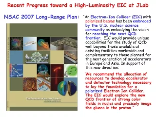
Great Opportunities Ahead of Us 12 GeV CEBAF Upgrade CD3 for upgrade approved, Construction already started Exciting fixed target program beyond 2020 What CEBAF will provide Up to 12 GeV CW electron beam High repetition rate (3x499 MHz) High polarization (>80%) Very good beam quality World first multi-pass recirculated SRF linac above GeV energy 12 GeV max energy 11 GeV max energy • Opportunity:Electron-Ion Collideron CEBAF • Add a modern ion complex with a Green Field design • Expand science program beyond 12 GeV CEBAF fixed target physics • Open up new science domain with higher CM energy
Science Motivation and Detector Requirements • Key issues in nucleon structure & nuclear physics • Sea quark and gluon imaging of nucleon with GPDs (x >~ 0.01) • Orbital angular momentum, transverse spin, and TMDs • QCD vacuum in hadron structure and fragmentation • Nuclei in QCD: Binding from EMC effect, quark/gluon radii from coherent processes, transparency • Machine/detector requirements • High luminosity > 1034: Low rates, differential measurements • CM energy: s ~ 1000 GeV2: Reach in Q2, x • Detactability: Angular coverage, particle ID, energy resolution favors lower, more symmetric energies!
ELIC Design Goals • Energy Wide CM energy range between 10 GeV and 100 GeV • Low energy: 3 to 10 GeV e on 3 to 12 GeV/c p (and ion) • Medium energy: up to 11 GeV e on 60 GeV p or 30 GeV/n ion and • High energy: up to 10 GeV e on 250 GeV p or 100 GeV/n ion • Luminosity • 1033 up to 1035 cm-2 s-1per interaction point • Multiple interaction points • Ion Species • Polarized H, D, 3He, possibly Li • Up to heavy ion A = 208, all striped • Polarization • Longitudinal at the IP for both beams, transverse of ions • Spin-flip of both beams • All polarizations >70% desirable • Positron Beamdesirable
Design Challenges & Opportunities Design an Electron-Ion Collider that Covers a wide CM energy range (10 to 100 GeV) in a unified & coherentway for highest science productivity Medium energy EIC is our immediate goal so it should be given first priority for maximum design optimization High energy EIC is a future goal so it should be leaved with greatest flexibility and upgrade potential Deliver best collider quality in terms of high luminosity, high polarization, multiple interaction points, maximum flexibility and reliability Takes maximum advantages of existing CEBAF Offers a good path for staging and future upgrade Requires minimum R&D and realizes in a most cost effective way Ion complex is a green field design so we have freedom to be innovative We can take benefit of knowledge learnt in the last several decades and incorporate many proofed great ideas/schemes in the design We have an opportunity to design a brand new class of hadron collider just we had done in CEBAF near twenty years ago.
Outline • Introduction • An EIC@JLab: 100<s<2600 with high luminosity • An EIC@JLab at High Energy: Design Update & Staging • More on EIC@JLab Design • EIC@JLab R&D • Summary
EIC@JLab at Low to Medium Energy • Three compact rings: • 3 to 11 GeV electron • Up to 12 GeV/c proton (worm) • Up to 60 GeV/c proton (cold)
polarimetry EIC@JLAB at Low to Medium Energy
WM City of NN State City of NN MEIC Footprint (~600m) SURA ELIC Footprint (~1800m) CEBAF ELIC Figure-8 Collider Ring Footprint Medium Energy IP Snake Insertion 60° Low Energy IP • Ring design is optimized with • Synchrotron radiation power of e-beam • prefers large ring (arc) length • Space charge effect of i-beam • prefers small ring circumference • Multi IPs require long straight sections • Straight sections also hold required components (e-cooling, injection and ejections, etc.)
Outline • Introduction • An EIC@JLab: 100<s<2600 with high luminosity • An EIC@JLab at High Energy: Design Update & Staging • More on EIC@JLab Design • EIC@JLab R&D • Summary
ELIC at High Energy & Staging p Ion Sources SRF Linac prebooster p p MEIC collider ring ELIC collider ring e e e injector 12 GeV CEBAF Interaction Point electron ring Ion ring Vertical crossing
EIC@JLab Parameters: High Energy Major design change: symmetric IR asymmetric IR
Outline • Introduction • An EIC@JLab: 100<s<2600 with high luminosity • An EIC@JLab at High Energy: Design Update & Staging • More on EIC@JLab Design • EIC@JLab R&D • Summary
ELIC Baseline Design Choice • Energy Recovery Linac-Storage-Ring (ERL-R) • ERL with Circulator Ring – Storage Ring (CR-R) • Back to Ring-Ring (R-R) by taking CEBAF advantage as full energy polarized injector • Reason of design change: High current polarized electron/positron source R&D too challenging • ERL-Ring: 2.5 A • Circulator ring: 20 mA • State-of-art: 0.1 mA Note we don’t have to have ERL in order to delivering high luminosity Key for high luminosity is high repetition, small beta* & short bunch • 12 GeV CEBAF Upgrade polarized source/injector already meets beam requirement of ring-ring design • CEBAF-based R-R design still preserves high luminosity, high polarization (+polarized positrons…)
Achieving High Luminosity ELIC design luminosity L~ 4x1034 cm-2 s-1 for medium energy (60 GeV x 3 GeV) L~ 1x1035 cm-2 s-1 for high energy (250 GeV x 10 GeV) ELIC luminosity Concepts • High bunch collision frequency (0.5 GHz, can be up to 1.5 GHz) • Short ion bunches (σz ~ 5 mm) (also much smaller bunch charge) • Relative long bunch (comparing to beta*) for very low ion energy • Strong final focusing (β*y ~ 5 mm) • Large beam-beam parameters (~0.01/0.1 per IP, 0.025/0.1 largest achieved) • Need electron cooling of ion beams • Need crab crossing colliding beams • Large synchrotron tunes to suppress synchrotron-betatron resonances • Equal (fractional) betatron phase advance between IPs
ELIC Ring-Ring Design Features • Unprecedented high luminosity • Electron cooling is an essential part of ELIC • Up to four IPs (detectors) for high science productivity • “Figure-8” ion and lepton storage rings • Ensure spin preservation and ease of spin manipulation • No spin sensitivity to energy for all species. • Present CEBAF injector meets storage-ring requirements • 12 GeV CEBAF can serve as a full energy injector to electron ring • Simultaneous operation of collider & CEBAF fixed target program. • Experiments with polarized positron beam are possible.
y z Figure-8 Straight Sections & Interaction Regions straight section spin rotator spin rotator vertical bend vertical bend e e collision point collision point arc bend arc dipoles ~0.5 m i i ~0.5 m Vertical crossing angle (~30 mrad) spin rotators vertical bend vertical bend Optional 2nd detector Minimizing crossing angle reduces crab cavity challenges & required R&D Interaction Region ~ 60 m IP FODO Chrom Chrom FF FF FODO Matching quads Matching quad Crab cavity Crab cavity Detector space
8 meters (for scale) 140 degrees Offset IP ID ~ length solenoid TOF HCAL PbWO4 ECAL Tracking No need for add’l dipole!: Q > 10o dipole RICH HCAL Add’l dipole field needed on ion side! solenoid Interaction Regions and Detectors Ent’s talk on ELIC detector design in this Workshop Magnetic Field in cold yoke around electron pass. Leant from LHeC Electron Proton 1st SC FF quad for ion (P. Brindza, ME) Electron FF quads 9 m Vertical crossing angle IP Electron FF quads
Outline • Introduction • An EIC@JLab: 100<s<2600 with high luminosity • An EIC@JLab at High Energy: Design Update & Staging • More on EIC@JLab Design • EIC@JLab R&D • Summary
EIC@JLab Accelerator R&D • We have identified the following critical R&D for ELIC • Electron cooling • Crab crossing and crab cavity • Forming high intensity low energy ion beam • Beam-beam effect • Traveling focusing for very low energy ion beam • Will discuss issues/requirements/state-of-art/challenges/activities
Electron Cooling: ERL Circulator Cooler Electron circulator ring • Issues • Essential for delivering ion bunches with small emittances and short length. • Cooling electron energy • up to 6.5 MeV for low energy ELIC • up to 33 MeV for medium energy ELIC • up to 136 MeV for high energy • Up to 3 A CW un-polarized beam (~nC bunch charge) • ERL Based Circulator Cooler • SRF ERL able to provide high average current CW beam with minimum RF power • Circulator ring for reducing average current from source/ERL • ERL Key technologies • High intensity un-polarized electron source/injector • Energy Recovery Linac (ERL) • Fast kicker • Beam Dynamics R&D (staged cooling) • State-of-Art • Fermilab electron cooling demo. (4.34 MeV, 0.5 A DC)
EC Enabling Technologies • High intensity e source/injector • 30 mA, up to 136 MeV, 1 nC bunch charge • Cathode lifetime is ok with circulator ring • Conceptual design adopts light source (FEL) photo-injector • Beam qualities should be OK • Fast kicker • RF deflecting cavity • High power ultra-short pulse • (sub-ns, 20kW) JLab FEL Gun R&D (J. Musson JLab, EE)
EC Enabling Technology: ERL JLab FEL Program Energy Recovery • ERL based FEL • High average power up to14 kW (world record) • mid-infrared region, extension to UV is planned • Photocathode DC injector, 10 mA class CW beam, sub-nC bunch charge • Beam energy up to 200 MeV, energy recovery • Next step/proposal: 100kW average power, 100 mA CW beam with ERL, nC-class bunch charge JLab is world leader in ERL technology ! We are considering using this facility to test ERL based circulator cooler ring and for beam dynamics studies
Crab Crossing & Crab Cavity Issues High bunch repetition requires crab crossing colliding beams to avoid parasitic beam-beam Crab cavities are needed to restore head-on collision and avoid luminosity reduction ELIC crossing angle: ~ 2x12mrad (9+9 m IR) • Crab cavity development & gradient limits • Phase & amplitude stability requirements • Beam dynamics/luminosity dependence of crab crossing State-of-art: KEKB Squashed cell@TM110 Mode Crossing angle = 2 x 11 mrad Vkick=1.4 MV, Esp= 21 MV/m
JLab Crab Cavity Development Multi-cell TM110 and Loaded Structure of Crabbing Cavity (JLab/Cockcroft/Lancaster) Elliptical squashed SRF cavity R&D for APS (JLab/LBNL/AL/Tsinghua Univ.) H. Wang, R. Rimmer, 12/10/2008 Moun Collider Design Workshop Single cell J. Delayen, H. Wang, PRST 2009 J. Delayen, JLab seminar, 02/19/09 • New (Innovative) Program • Compact TEM-type, parallel-bar • Deflecting 12 GeV CEBAF • Crabbing ELIC • Providing high transverse kinking • Single cell: 37x50cm, 4 MV@500MHz • Multi-cell: ~ n x (37 cm), n x (4 MV) E&M Fields Multi cell
Great News From KEK KEK Press Release (05/11/09) “Using Crab Cavities, KEKB Breaks Luminosity World Record” SymmetryBreaking(05/11/09) “Record luminosity collisions due to “crab” crossing, Trick: 28 skew sextupoles
Forming High Intensity Ion Beam Stacking/accumulation process • Multi-turn (~20) pulse injection from SRF linac into an accumulator-cooler ring • Damping/cooling of injected beam • Accumulation of 1 A coasted beam at space charge limited emittence • Fill prebooster/large booster, then acceleration • Switch to collider ring for energy booster, RF bunching and initial/continuous cooing Stacking proton beam in ACR In addition to simulation study, we are considering team up with ORNL to study space charge effect at SNS
Beam-Beam Interactions Low-to-medium energy b-b problem Non-relativistic, space charge dominated Ring transport can’t be treated as a one-turn map, coupling everywhere Long ion bunch (up to 20 x β*), longitudinal dynamics important Traveling focusing scheme introduces non-linear optics ~Dip-ip 4 16 15 3 5 17 14 4 2 16 3 15 5 17 18 6 13 1 2 14 6 18 13 1 12 24 19 7 7 11 19 12 23 24 20 8 10 22 9 21 23 Dip-ip 11 8 20 10 22 21 9 • Simulation Model • Single/multiple IP, head-on collisions • Ideal rings for e & p, a linear one-turn map • Radiation damping & quantum excitations • Simulation Codes • BeamBeam3D by LBNL • Simulation Scope & Limitations • 10k ~ 30k turns for a typical simulation run • (multi-days of NERSC supercomputer) • 0.15 s of storing time (12 damping times) • reveals short-time dynamics with accuracy • can’t predict long term (>min) dynamics 70% of peak luminosity My talk in this Workshop Coherent instability
Boosting luminosity at low ion energy: Traveling Final Focusing/Crab Waist Traveling Final Focusing Laslett tune-shift limits bunch charge for very low energy ions (space charge dominated) Long bunch length enables more bunch charges, therefore high luminosity Hour glass effect could kill luminosity if bunch length is much large than beta-star “Traveling Focusing” (Brinkmann/Dohlus), can mitigate hour-glass effect New realization: crab crossing beam with sextuples x b Y e - e+ s q 2 / x q s q 2 * z z s 2 z s 2 x Crab cavity slice 2 F1 slice 1 slice 2 sextuple F2 slice 1 • Crab Waist • Proposed by P. Raimondi for Super-B factory for luminosity enhancement • It deals with large Piwinski angle and low vertical beat-star • Current Super-B design calls 0.2 mm beta-star while bunch length is 6 mm • Recent proof-of-principle experiment done at DAΦNE very positive Crabbed waist can be realized with a sextupole in with IP in x and at π/2 in y
Summary • EIC@JLab promises to accelerate and store a wide variety of polarized light ions and un-polarized heavy ions to collider with polarized electron or positron beam enabling a unique physics program. • The ELIC covers a wide CM energy range (10 to 100 GeV) in a coherent way. However, the low-to-medium energy one (CM energy 10 to 50 GeV) is our immediate goal & R&D focus. • EIC@JLab luminosity for e-p collisions should exceed 1x1035 cm-2s-1 at high energy end (250x10 GeV2), reach 4x1034 cm-2s-1 at medium energy (60x3~5 GeV2),and 6x1033 cm-2s-1 at low energy end (12x3 GeV2) • Positron beam can also be used for additional positron-ion and electron-positron collision programs. Both electron & positron beam possess high (>80%) polarization. • We have identified the critical R&D topics for EIC@JLab. In general, R&D for the medium energy EIC is much easy than for high energy one, which also provides a nice staging approach for accelerator R&D. We are aggressively pushing R&D programs to validity and optimize ELIC design ELIC is the primary future of JLab!
ELIC Study Group A. Afanasev, A. Bogacz, J. Benesch, P. Brindza, A. Bruell, L. Cardman, Y. Chao, S. Chattopadhyay, E. Chudakov, P. Degtiarenko, J. Delayen, Ya. Derbenev, R. Ent, P. Evtushenko, A. Freyberger, D. Gaskell, J. Grames, L. Harwood, T. Horn, A. Hutton, C. Hyde, R. Kazimi, F. Klein, G. A. Krafft, R. Li, L. Merminga, J. Musson, A. Nadel-Turonski, M. Poelker, R. Rimmer, C. Tengsirivattana, A. Thomas, M. Tiefenback, H. Wang, C. Weiss, B. Wojtsekhowski, B. Yunn, Y. Zhang - Jefferson Laboratory staffs and users W. Fischer, C. Montag - Brookhaven National Laboratory D. Barber - DESY V. Danilov - Oak Ridge National Laboratory V. Dudnikov - Brookhaven Technology Group P. Ostroumov - Argonne National Laboratory V. Derenchuk - Indiana University Cyclotron Facility A. Belov - Institute of Nuclear Research, Moscow, Rssia V. Shemelin - Cornell University
Green-field design of ion complex directly aimed at full exploitation of science program. ELIC Conceptual Design Accumulator-cooler ring & prebooster 30-250 GeV protons 15-100 GeV/n ions 3-10 GeV electrons 3-10 GeV positrons 12 GeV CEBAF Upgrade
spin rotator spin rotator 180ºspin rotator collision point collision point 180ºspin rotator spin rotator spin rotator Solenoid spin rotator Vertical bending dipole Solenoid spin rotator Vertical bending dipole spin e Spin tune solenoid spin tune solenoid e i i Arc bending dipoles Arc bending dipoles 90º 90º spin tune solenoid spin tune solenoid Vertical bending dipole Vertical bending dipole Spin rotators Electron Polarization Producing/matching • Polarized electron source of CEBAF • Preserved in recirculated CEBAF • Injected into Figure-8 ring with vertical polarization • Turn to longitudinal polarization at IP using vertical crossing bends and solenoid spin rotators Maintaining in the ring • electron self-polarization • SC solenoids at IRs removes spin resonances & energy sensitivity.
converter 10 MeV 5 MeV e+ Transverse emitt. filter Longitudinal emitt. filter Polarized source e- 15 MeV e- e - e- e+ dipole dipole 115 MeV dipole 15 MeV e+ During positron production: - Polarized source is off - Dipoles are turned on Unpolarized source Positrons in CEBAF/ELIC • “CEPBAF”, S. Golge (Ph. D thesis) / A. Freyberger • Polarized Positron Source, J. Dumas (Ph.D thesis) /J. Grames • Joint JLab/Idaho Univ. Position Program International Workshop on Positrons at Jefferson Lab March 25-27, 2009 • Non-polarized positron bunches generated from modified electron injector through a converter • Polarization realized through self-polarization at ring arcs (M. Polker)