Download
1 / 42
430 likes | 591 Views
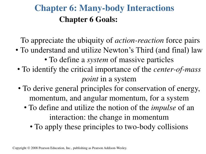
Chapter 6: Many-body Interactions. Chapter 6 Goals:. To appreciate the ubiquity of action-reaction force pairs To understand and utilize Newton’s Third (and final) law To define a system of massive particles To identify the critical importance of the center-of-mass point in a system

E N D
Chapter 6: Many-body Interactions Chapter 6 Goals: • To appreciate the ubiquity of action-reaction force pairs • To understand and utilize Newton’s Third (and final) law • To define a system of massive particles • To identify the critical importance of the center-of-mass point in a system • To derive general principles for conservation of energy, momentum, and angular momentum, for a system • To define and utilize the notion of the impulse of an interaction: the change in momentum • To apply these principles to two-body collisions
Newton’s Third law • ‘to every action, there is an equal and opposite [sic] reaction’ • by ‘action’ we mean a force (and therefore a momentum change) • the actions occur on/to DIFFERENT bodies: the bodies are said to interact • How? strings… contact… springs… COLLISIONS • FBA = ─ FAB The 2 forces on the monitor, and their Newton’s-third-law counterparts
Example The pair of blocks accelerates at 5 m/s2. Find all of the forces on both blocks. F Note that R12 = ─ R21 15 kg N2 5 kg N1 FBD 1 N1 = m1g =50 N F ─ R21 = m1a = 25 N FBD 2 N2 = m2g = 150 N R12 = m2a = 75 N But R12 = R21= 75N and so from above, F = 100N R12 R21 F W1 W2
Example 5 kg The pair of blocks accelerate. The coefficient of kinetic friction is 0.40. Find a and T. String and pulley are ideal. Note that T12 = ─ T21 15 kg • FBD 1 N1 = m1g = 50 N • ─ FK + T21 = m1a • and note FK = mKN1 = 20 N • so T21 = 20 N + 5kg a • FBD 2 ─ T12 + m2g = m2a • So T12= 150 N ─15 kg a • But T12 = T21so we get • 20 N + 5kg a = 150 N ─ 15 kg a • a = 130 N/ 20 kg = 6.5 m/s2 • T = 20 N + (5 kg)( 6.5 m/s2) • = 52.5 N N1 T12 T21 FK W1 W2
A system of masses and their felt forces • a system is a collection of N masses {mi} i = 1, 2, 3,…, N • each one feels both internal and external forces • Take the time derivative of P, using sum rule • first term: total external force on system • second term: messy double sum that contains all pairs of internal forces added up , like f12 + f21 +…
Newton’s action-reaction pairs for two bodies • the forces may be central (like gravity or electric) • but they don’t have to be (like magnetism) • they may be gigantic and short-lived (like collisions) • for this situation we will introduce the useful notion of the impulse of a force • there are exceptions in advanced electricity due to the finite speed of light
A system of masses and the forces on it • by N3, f12 = ─ f21 : the entire double sum adds to zero!! • in English: the internal forces in a system add to zero and thereforce cannot affect the momentum of the system!! • important special case: if FEXT = 0 (either because there are no external forces, of because they happen to add to 0) • an extremely powerful conservation law that relies on the truth of N3 and permits one to not worry too much about the internal doings of a system or extended body
The center of mass of a system M = ∑mi • Let the positions of the bodies be given by {ri} • very cool!! The system momentum is the simply the system mass times the velocity of center of mass!!
Further implications, and where is it? • very cool!! The rate of change of system momentum is the simply the system mass times the acceleration of the center of mass!! • And if FEXT = 0, it’s N1 time!! No matter what the system is doing (spinning, writhing, exploding… the center of mass just cruises along without accelerating • but.. where is the center of mass?? • example: two bodies. Where is c.o.m.? • answer: along the line joining the bodies, between them, and closer to the more massive body
Where is it for the two-body problem? • the primed positions have the c.o.m. as their origin • both primed positions are vectors parallel to the vector that starts on one body and ends on the other • they are both shorter than that vector and proportional in length to the other mass/M • they are in opposite directions • Thus, the c.o.m. lies where we said it did • For N > 2, the c.o.m. is a ‘weighted’ position average and visualizable at least: see figure next slide
Three bodies much more complicated r’1 r1 C C r’2 r1–r2 r1 r2 r3 r2 O O {show Active Figure 09_14}
Not in book: the idea of the impulse • The impulse J delivered to any body in an interaction is the change in momentum of that body Dp • it is the net force Fnet(t) that one graphs • interaction duration Dt • useful for very rapid high-force situations • The impulse is the area under Fnet(t) graph
More about the impulse • if the graph is a simple shape (triangle, rectangle) one gets the area easily • if a triangle, J = bh/2 = (Dt)(Fnet,max)/2 so we see that Fnet,max = 2J/ Dt • for any shape graph, the average net force is given by < Fnet> = J/ Dt from the rectangle’s area Fnet,max
Example Assume the collision lasts for .25 s. The car’s mass is 800 kg and Fnet(t) has a triangular shape. The net force is essentially the collision force since it is dominant. Find the impulse delivered to the car, and <F> and Fmax .
The reducedmass of a two-body system • a way to replace the motions of the pair of bodies, as seen from a fixed origin, with the motion of one of the bodies (here, #1), as seen relative to a moving origin located at the other body (here, #2) • of course, the moving origin is probably accelerating so it is not an inertial frame • the kinematics (motion) is straightforward • the dynamics (forces) may require fictitious forces to explain the kinematics • we start with the origin at the c.o.m. and we define r to be the vector from #2 to #1: r := r1─ r2 • thus, r is the position of r1relative to r2 • recall that the primed positions are parallel to r
Some remarks about the notation • Relative to the fixed origin O • positions relative to O are ri • velocities relative to O are vi := dri/dt • accelerations relative to O are ai := dvi/dt • Relative to the c.o.m. origin • positions relative to c.o.m. are r’i:= ri– RC • velocities relative to c.o.m. are ui := vi– VC • accelerations relative to c.o.m. are a’i := ai– AC • For the two-body problem • position of m1 relative to m2 is r = r1– r2[= r’1– r’2] • velocity of m1 relative to m2 is u =u1– u2[= v1– v2] • acceleration of m1 relative to m2 is a = a1– a2 [=a’1– a’2]
The reducedmass II • let the internal net forces be F21 = ─ F12 := F • a1 = F/m1 ;a2 = ─ F/m2 a = a1 ─ a2 = F/m1 + F/m2 • common denominator: a = F(m1+m2)/m1m2 • m is called reduced mass; m < m1 and m < m2 • the motion of m1 as seen from an origin on m2 is controlled by F, but it is as if there is only one body moving, and that body has the reduced mass!!
The reducedmass III • rephrase K1: when 2 bodies orbit, they both move on (different) ellipses, with c.om. at common focus • here, the two stars have comparable masses so the c.om. is near the center, and the reduced mass is about half of either mass taken alone • in general, m is less than and closer to the smaller mass
The reducedmass IV • obviously, VC = dRC/dt ; againvi = dri /dt • then u = dr/dt = v1 ─ v2 since r = r1 ─r2 • now consider VC ─ vi , which is the velocity of c.o.m. as seen from body i (we’ll do #1 and #2) • you can get the same stuff just by taking d/dt of our previous r1 andr2 equations much more easily • note that we have re-expressed velocities in terms of c.o.m velocity VC and relative velocity u
What happens to system kinetic energy? • definition is straightforward; the interpretation less so • term 2 has velocity of c.o.m. relative to c.o.m. = 0 two terms for K: kinetic energy of the center of mass (as if system were a point mass M moving at c.o.m. velocity VC) plus kinetic energy relative to the c.o.m.
What happens to two-body kinetic energy? • look at the second term and re-express in terms of u • two terms for K: kinetic energy a body of mass M moving at VC, plus kinetic energy of a body of mass m moving at u: the two-body problem is effectively now a one-body problem, if you observe from the c.o.m. • recall system momentum: much simpler P = MVC
What happens to the system potential energy?What about the mechanical energy conservation? • If definable, U is a function of position only • U = U(r1 ,r2) could include internal and external forces • If the forces are only internal and central and vary only with separation distance (common!) we say more: • U(r1 ,r2) = U(|r1 ─r2|) = U(|r|) = U(r) so we have • but there is no external force: the first term can’t change
What happens to system angular momentum? • proceed as we have been doing, writing positions ri as c.o.m. position plus positions referred to c.o.m [and for vi] • term 2 contains velocity of c.o.m. as seen from c.o.m = 0 • term 3contains position of c.o.m. as seen from c.o.m = 0 = ang mom of c.o.m + ang mom relative to c.o.m
How does system angular momentum change? • take the time derivative of the system ang mom • term 2: assume N3 so there are terms like (ri ─ ri) x fji = vector from j to i crossed into fji • further assume central forces, so those two vectors are parallel: entire double sum is zero!!
How does system angular momentum change? • if there are no external torques (or if they add to zero) then angular momentum of the system is conserved Process L to express in terms of reduced mass • look at the second term and re-express in terms of u
Summary of the system quantities • system momentum is P = MVC • it can only change if (F)EXT ≠ 0 • two-body kinetic energy • system kinetic energy • two-body angular momentum • system angular momentum • it can only change if (M)EXT ≠ 0 • if c.o.m. obeys N1 there is an inertial frame, called the center-of-mass frame, from which the physics is particularly simple (since the c.o.m. is stationary!!)
Important scenario: the two-body collision in 1d • m1and m2 collide and all motion is in 1d • velocities before collision are u1 and u2 (known) • velocities after collision are v1 and v2 (not known) • momenta before collision are p1 and p2 • momenta after collision are q1 and q2 • during collision, all important forces are internal • therefore system momentum is conserved! v2 ; q2 v1 ; q1 u1 ; p1 u2 ; p2
The elastic collision in 1d • if DE = 0 DK = 0 too (DU = 0 too because there is no height change) elastic collision • conventional approach is to derive expressions for the final velocities v1 and v2 in terms of the masses m1 and m2 and the initial velocities u1 and u2 • there are two conditions to impose: system momentum conservation, and kinetic energy conservation two equations in two unknowns • trouble is, one of them is ‘quadratic’ statement so the arithmetic is very tricky • Watch carefully…
The totally inelastic collision in 1d • if maximum energy is lost totally inelastic collision • the bodies stick together, so velocities v1 = v2 := v • there is only one condition to impose: system momentum conservation conservation one equation • proving thatmaximum energy is lost ifthe bodies stick together is not so easy unless one ‘goes to’ the center of mass frame of reference • this is alluded to in the book… we will illustrate!
The totally inelastic collision in 1d as expressed relative to the c.o.m • result is obvious: c.o.m. is motionless in c.o.m frame • there is NO kinetic energy left as seen in this frame
Important case: initially stationary m2 (u2 = 0) • elastic collision is worked out in example 6.3 (p 135) • totally inelastic collision is simplicity itself {show active figures 09_05-07}
Example Problem 6.3 Two crates (masses 300 kg and 100 kg), joined by a light rope, are being pulled along a factory floor by a constant force exerted on the heavier crate at an angle of 25° to the horizontal. The coefficient of kinetic friction between the heavier crate and the floor is 0.11 and that between the lighter crate and the floor is 0.18. What should the magnitude of the applied force be to move the crates at constant speed? What applied force would be required to give the system an acceleration of 0.10 m/s2? What would the tension in the rope be in both cases? 300 kg 100 kg
Example 6.6 A glider of mass 180 g travelling on a horizontal airtrack at a speed of 3.0 m/s catches up with another glider of mass 360 g moving in the same direction at 0.9 m/s. If 10% of the energy is lost in the collision what are the speeds of the gliders after the collision?
Example cont’d Plug both of these into the v2 equation:
Example cont’d The other answer would have come from the 360 g mass moving in the opposite direction initially. This would have slowed down the 180 g mass a lot more, but would have corresponded to the same kinetic energy intially. So the quadratic nature of the kinetic energy introduces subtleties! Example 5.17 A 200 g block is constrained to move on a smooth horizontal table by a string that passes downward through a hole in the centre of the table. Its speed is 0.5 m/s and radius is 0.4 m. The string is pulled to reduce the radius to 0.3 m. What is new speed? How much work is done by the puller?
Example 5.17 cont’d • find the net torque on the body as seen from the hole as origin • MT = r x T MT = rT sin 180° = 0 • MW= r x W MW = rmgsin 90° = rmg • direction is anti-parallel to p • clearly, N = – W so MN = rmgsin 90° too • but direction is parallel to p • net torque Mnet = 0 L is conserved TOP VIEW p r T O • L = r x p L = mvr sin 90° = mvr; direction is ‘down’
Example 5.17 cont’d • find the net torque on the body as seen from the hole as origin • MT = r x T MT = rT sin 180° = 0 • direction is immaterial! • MW= r x W MW = rmgsin 90° = rmg • direction is anti-parallel to p • clearly, N = – W so MN = rmgsin 90° too • but direction is parallel to p • net torque Mnet = 0 L is conserved • L = r x p L = mvr sin 90° = mvr • direction is into table: ‘down’
Example of a two-body system I A mass m1 = 500 g moves at 4.0 m/s to the right, and collides elastically with a mass m2 = 1500 g moving to the left at 2.0 m/s. a) Find system P and K in this frame b) Find the c.o.m velocity and the reduced mass c) Find the quantities in (a) using M and m d) Find the relative-to-c.o.m velocities and the same 4 quantities relative to (“in”) the c.o.m. frame e) confirm that P and K are conserved in the original frame
Example of a two-body system II c) Find the quantities in (a) using M and m d) Find the relative-to-c.o.m velocities and the same 4 quantities relative to (“in”) the c.o.m. frame
Example of a two-body system III e) confirm that P and K are conserved in the original frame one can confirm that P and K are conserved in the c.o.m. frame…..