Download
1 / 35
350 likes | 509 Views
Laser &Optics of LCGT. 2011/10/5(Wed) Norikatsu Mio Photon Science Center University of Tokyo. Schematic View of LCGT Optical System. ETMY. Laser. MC1. MC3. ITMY. MT1. PRM. PR1. ITMX. ETMX. MT2. BS. PR2. SR1. MC2. SRM. SR2. Laser. Requirements for the laser. Power > 180 W

E N D
Laser &Optics of LCGT 2011/10/5(Wed) Norikatsu Mio Photon Science Center University of Tokyo EGO-ICRR Meeting 2011/10/4-5
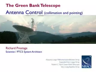
Schematic View of LCGT Optical System ETMY Laser MC1 MC3 ITMY MT1 PRM PR1 ITMX ETMX MT2 BS PR2 SR1 MC2 SRM SR2 EGO-ICRR Meeting 2011/10/4-5
Laser EGO-ICRR Meeting 2011/10/4-5
Requirements for the laser • Power > 180 W • Single frequency • Linear polarization • Single transverse mode • Wide-band control for stabilization systems • About 1MHz for frequency control • About 100kHz for intensity control EGO-ICRR Meeting 2011/10/4-5
Injection Lock or MOPA • Single frequency laser output over 100 W CW can be realized by using injection-locking and MOPA. • Injection locking has many advantages compared with MOPA. • However, an injection locking system is more complex than a MOPA system; this is quite critical for easy operation. • We have a 10-year history developing a prototype based on the injection-locking scheme. • We recognized that the injection-locking system is quite sensitive to the alignment and it seemed to be difficult to keep the best performance without a well-trained operator. • MOPA is easy for assembly and maintenance. EGO-ICRR Meeting 2011/10/4-5
Design for the system • An amplifier system consisting of a seed laser (NPRO), fiber amplifiers and solid-state amplifiers will be used. • Fiber laser technology is rapidly progressed and its power level may arrive at the requirement soon even though the current fiber amplifiers have some problems. • Combination of the fiber laser technology and the solid state laser technology is our current choice. • If high-power, long life-time and narrow line-width fiber amplifiers are available, solid-state amplifiers can be replaced. • Korean Group (Prof. Yoon @ Korea University) is willing to develop a part of the laser system, in particular, a high-power fiber laser. EGO-ICRR Meeting 2011/10/4-5
Schematic diagram Mitsubishi laser modules 200 W 80 W Fiber laser amplifiers 40 W NPRO(500mW) 40 W EGO-ICRR Meeting 2011/10/4-5
Commercial fiber amplifier EGO-ICRR Meeting 2011/10/4-5
Laser module (Mitsubishi) Diffusive reflector +LD Two rods and rotator EGO-ICRR Meeting 2011/10/4-5
Laser • Most of the main elements will be obtained by the end of this FY. • Discussion will start with a company that will assemble the laser system using Mitsubishi modules and fiber amplifiers, soon. • The first laser will be hopefully completed at the end of FY 2012 (March, 2013). • Green lasers used for “GREEN-LOCK” will be prepared at the end of this FY. EGO-ICRR Meeting 2011/10/4-5
Current Status Chiller Power Supply 200 W Mitsubishi laser modules 80 W Fiber laser amplifiers 40 W NPRO(500mW) 40 W EGO-ICRR Meeting 2011/10/4-5 Light Green: Obtained Green: Ordered
Schedule EGO-ICRR Meeting 2011/10/4-5
TODO • Performance of the fiber amplifier • 10-W one is OK but 40-W one has not been tested. • Performance of the coherent addition system • The fringe contrast, phase stability and so on. • Performance of the laser module when used as an amplifier. • Optimization of the beam profile for obtaining the best amplification performance. • Polarization stability, noise level should be tested. • Fix the specifications for the control system (interfaces to a PC and other systems) EGO-ICRR Meeting 2011/10/4-5
Optics EGO-ICRR Meeting 2011/10/4-5
Mirror Core optics of LCGT ETMY f10cm Mirrors for Main cavities Initial: Silica Final: Sapphire Laser MC1 MC3 ITMY MT1 PRM PR2 ITMX ETMX MT2 BS PR3 SR2 MC2 f38cm SRM SR3 f 25cm EGO-ICRR Meeting 2011/10/4-5
Optics • Substrates(Silica, Sapphire) • Polish & Coating & Measurement • iLIGO Mirrors EGO-ICRR Meeting 2011/10/4-5
Substrate (Silica) • Asahi Glass Company (AGC), AQ and AQ2 will be used. • BS (f38cm x t12cm, AQ2): obtained! • MC (f10cm x t3cm, AQ2 and AQ): obtained! • Delivery was delayed owing to the earthquake because the factory of AGC is locatedin Koriyama (郡山). • New substrates for ITMs (f25cm x t10cm, AQ2) have been ordered. EGO-ICRR Meeting 2011/10/4-5
AGC:AQ2 IR performance of AQ2 is comparable to Sprasil. At UV, its performance is better than Sprasil. EGO-ICRR Meeting 2011/10/4-5 18
Substrate (Sapphire) • A-axis crystal (f25cm x t15cm) has been ordered. • Max size of C-axis crystal is now f22cm x t15cm; this size is limited by the height of the boules. Response from CSI at the beginning of 2011 • Current Max size of • C-axis mirror: f20cm x t15cm • A-Plane mirror: f25cm x t15cm “With time we feel can develop larger C-axis sapphire slabs to achieve your goal of 25cm x 15cm sapphire mirrors with our HEM growth process.” Optical Absorption <20 ppm/cm (10 ppm/cm is preferable Absorption is still unclear; new small samples are being tested. EGO-ICRR Meeting 2011/10/4-5
Photo-thermal deflection method C-axis f: 100 mm x t: 60 mm Z=50mm, 53.4 ppm/cm Z=40mm, 45.5 ppm/cm Z=30mm, 47.3 ppm/cm Z=20mm, 46.1 ppm/cm Z=10mm, 54,2 ppm/cm Z=30mm (2005) EGO-ICRR Meeting 2011/10/4-5
Sapphire absorption at cryogenic temperature By Tomaru @ KEK in 2000 EGO-ICRR Meeting 2011/10/4-5
Absorbed light power Sample tempature change Refraction Index, length change Optical path length change Absorption measurement@UT Chopped light is incident on a sample. 120Hz Signal is lock-in detected. Lock-in Amplifier Laser l:1064nm Power:10W Chopper Sample BS(R=98%) BPF LPF PD Dark fringe 15kHz Mirror PZT PZT driver Filter EGO-ICRR Meeting 2011/10/4-5 22
Interferometer Laser light 2010/9/14 EGO-ICRR Meeting 2011/10/4-5 23
Sapphire sample • C-axis rod (diameter: 10mm, length: 40mm) EGO-ICRR Meeting 2011/10/4-5
Results of Sapphire Measurement in last year Measurement in this year 80ppm/cm 87ppm/cm The result was reproduced but the noise level of the interferometer became worse; the origin of the noise has not been identified. Calibration for sapphire has not been done Absolute values may contain large uncertainty! EGO-ICRR Meeting 2011/10/4-5
Preliminary results 10 Samples Name Absorption [ppm/cm] preliminary • AA149 and P401 show better performance compared with the last year sample. • AC150 shows quite high absorption; why ? • P401 contains lower and high absorption pairs. what is the difference? EGO-ICRR Meeting 2011/10/4-5
Polish & Coating & Measurement • Members of AIST-NMIJ are collaborating with us ; a mirror used in LISM (R=30 m) has been sent to NMIJ to evaluate the absolute value of its curvature radius. • Memorandum for the collaboration about the polishing with Riken group has fixed. • We are still looking for the facilities for polishing and coating. EGO-ICRR Meeting 2011/10/4-5
Requirements for Roughness Allowable loss of main mirrors: 45 ppm Scattering loss < 30 ppm Total Integrated Scattering Spatial spectrum of surface roughness Hiro Yamamoto@ LIGO Is kindly collaborating about this issue. Spatial distribution of the surface roughness can be express as a function of spatial wave number. AdvLIGO 28 EGO-ICRR Meeting 2011/10/4-5
Example of Superpolished Surfacedone by Japanese Company Substrate: Zerodur Diameter: 25 cm Thickness: 4cm Surface roughness: 0.12 nm rms Size: 0.14mm x 0.1mm Requirement: 0.5 nm within 12cm 29 EGO-ICRR Meeting 2011/10/4-5
Requirement for coating • Main mirrors • Absorption: < 1 ppm=> Heating problem • Scattering: < 30ppm • Beam splitter and Recycling Mirrors • Loss < 0.01 % • Thermal noise issue is out of scope for iLCGT. • This issue seems to be taken into consideration seriously even for cryogenic mirrors of bLCGT ; Ta and Ti co-doping??? EGO-ICRR Meeting 2011/10/4-5 30
iLCGT mirrors from iLIGO For iLCGT, the size of the mirrors is chosen as that of iLIGO’s mirror. BS and ITMs will be newly fabricated from Japanese Silica. LIGO kindly donates the mirrors to us. EGO-ICRR Meeting 2011/10/4-5
Telescope used in iLIGO arrived The mode reducing telescope used in iLIGO arrived at ICRR on August 22, 2011. The Mirrors used in iLIGO will be sent to Japan, soon. EGO-ICRR Meeting 2011/10/4-5
Schedule EGO-ICRR Meeting 2011/10/4-5 33
Miscellaneous on Optics • We need further R&D for sapphire. • Members of AIST-NMIJ are willing to collaborate with us concerning the surface profile measurement. • A few Japanese companies are willing to fabricate the mirrors of LCGT; they have some experiences for high precision optics. • Test facilities for optical absorption and optical scattering will be kept. EGO-ICRR Meeting 2011/10/4-5
Summary • Preparation of the laser system is going well. • Silica substrates will be obtained soon. • Preparation of the sapphire crystals needs further efforts and days. • Polishing and coating are still issues that should be solved as soon as possible. • We would deeply appreciate to the international collaborations. In particular, collaborations from VIRGO/EGO EGO-ICRR Meeting 2011/10/4-5