Download

1 / 39
390 likes | 530 Views
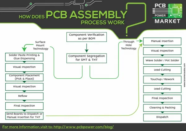
The Assembly Process Basically how does it all work. The Assembly Process. Machine code. Assembly code. A computer understands machine code - binary People (and compilers) write assembly language. Assembler. The Assembly Process.

E N D
The Assembly Process Machine code Assemblycode • A computer understands machine code - binary • People (and compilers) write assembly language Assembler 2
The Assembly Process • An assembler is a program that translates each instruction to its binary machine code equivalent. • It is a relatively simple program • There is a one-to-one or near one-to-one correspondence between assembly language instructions and machine language instructions. • Assemblers do some code manipulation • Like MAL to TAL • Label resolution • A “macro assembler” can process simple macros likeputs, or preprocessor directives. 3
MAL TAL • MAL is the set of instructions accepted by the assembler. • TAL is a subset of MAL – the instructions that can be directly turned into machine code. • There are many MAL instructions that have no single TAL equivalent. • To determine whether an instruction is a TAL instruction or not: • Look in appendix C or on the MAL/TAL sheet. • The assembler takes (non MIPS) MAL instructions and synthesizes them into 1 or more MIPS instructions. 4
MAL TAL • For example • Becomes • MIPS has 2 registers for results from integer multiplication and division: HI and LO • Each is a 32 bit register • mult and multu places the least significant 32 bits of its result into LO, and the most significant into HI. • Multiplying two 32-bit numbers gives a 64-bit result • (232 – 1)(232 – 1) = 264 – 2x232 - 1 mul $8, $17, $20 mult $17, $20mflo $8 5
MAL TAL mflo, mtlo, mfhi, mthi Move From lo Move To hi • Data is moved into or out of register HI or LO • One operand is needed to tell where the data is coming from or going to. • For division (div or divu) • HI gets the remainder • LO gets the dividend • Why aren’t these just put in $0-$31 directly? 6
MAL TAL TAL has only base displacement addressing So this: lw $8, label Becomes: la $7, label lw $8, 0($7) Which becomes lui $8, 0xMSPART of label ori $8, $8, 0xLSpart of label lw $8, 0($8) 7
MAL TAL • Instructions with immediate values are synthesized with other instructions • So: add $sp, $sp, 4 • Becomes: addi $sp, $sp, 4 • For TAL: • add requires 3 operands in registers. • addi requires 2 operands in registers and one operand that is an immediate. • In MIPS assembly immediate instructions include: • addi, addiu, andi, lui, ori, xori • Why not more? 8
MAL TAL TAL implementation of I/O instructions This: putc $18 # if you got to use macros Becomes: addi $2, $0, 11 # code for putc add $4, $18, $0 # put character argument in $4 syscall # ask operating system to do a function 9
MAL TAL getc $11 Becomes: addi $2, $0, 12 syscall add $11, $0, $2 puts $13 Becomes: addi $2, $0, 4 add $4, $0, $13 syscall done Becomes: addi $2, $0, 10 syscall 10
MAL TAL 11
MAL TAL 12
Assembler • The assembler will: • Assign addresses • Generate machine code • If necessary, the assembler will: • Translate (synthesize) from the accepted assemblyto the instructions available in the architecture • Provide macros and other features • Generate an image of what memory must look like forthe program to be executed. 13
Assembler • What should the assembler do when it sees a directive? • .data • .text • .space, .word, .byte, .float • main: • How is the memory image formed? 14
Assembler • Example Data Declaration • Assembler aligns data to word addresses unless told not to. • Assembly process is very sequential. .dataa1: .word 3 a2: .byte ‘\n’ a3: .space 5 Address Contents 0x00001000 0x00000003 0x00001004 0x??????0a 0x00001008 0x???????? 0x0000100c 0x???????? 15
Machine code generation Assembly language: addi $8, $20, 15 immediate opcode rt rs Machine code format: 31 0 opcode rs rt immediate • opcode is 6 bits – addi is defined to be 001000 • rs – source register is 5 bits, encoding of 20, 10100 • rt – target register is 5 bits, encoding of 8, 01000 • The 32-bit instruction for addi $8, $20, 15 is: • 001000 10100 01000 0000000000001111 • Or • 0x2288000f 16
Instruction Formats • I-Type Instructions with 16-bit immediates • ADDI, ORI, ANDI, … • LW, SW • BNE OPC:6 rs1:5 rd:5 immediate:16 OPC:6 rs1:5 rs2/rd displacement:16 OPC:6 rs1:5 rs2:5 distance(instr):16 17
Instruction Formats • J-Type Instructions with 26-bit immediate • J, JAL • R-Type All other instructions • ADD, AND, OR, JR, JALR, SYSCALL, MULT, MFHI,LUI, SLT OPC:6 26-bits of jump address OPC:6 rs1:5 rs2:5 rd:5 ALU function:11 18
Assembly Example “Symbol Table” .data a1: .word 3 a2: .word 16:4 a3: .word 5 .text main: la $6, a2 loop: lw $7, 4($6) mul $8, $9, $10 b loop done 19
Assembly Example Memory map of .data section 20
Assembly Example Translation of MAL to TAL code .textmain: lui $6, 0x0040 # la $6, a2 ori $6, $6, 0x0004 loop: lw $7, 4($6) mult $9, $10 # mul $8, $9, $10 mflo $8 beq $0, $0, loop # b loop ori $2, $0, 10 # done syscall 21
Assembly Example Memory map of .text section 22
Assembly Example Branch offset computation • At execution time: PC NPC + {sign extended offset field,00} • PC points to instruction after the beq when offsetis added. • At assembly time: • Byte offset = target addr – (address of branch + 4) • = 00800008 – (00800010 + 00000004) • = FFFFFFF4 (-12) 23
Assembly Example 4 important observations: • Offset is stored in the instruction as a word offset • An offset may be negative • The field dedicated to the offset is 16 bits, range is thus limited • More simply: Just count the number of instructions from instruction following branch to target, encode that as a 16-bit value 24
Assembly Jump target computation • At execution time: • PC {most significant 4 bits of PC, target field, 00} • At assembly time: • Take 32 bit target address • Eliminate least significant 2 bits (since word aligned) • Eliminate most significant 4 bits • What remains is 26 bits, and goes in the target field 25
Linking N’ Loading The process of building/configuring the executable, placing it in memory, and running it. 26
Linking and Loading Linker • Searches libraries • Reads object files • Relocates code/data • Resolves external references • Creates object file 27
Linking and Loading Loader • Creates address spaces for text & data • Copies text & data in memory • Initializes stack and copy args • Initializes regs (maybe) • Initializes other things (OS) • Jumps to startup routine • And then to address of “main:” 28
Linking and Loading Object file 29
Linking and Loading • The data section starts at 0x0040 0000 for the MIPS processor. • If the source code has, • .data • a1: .word 15 • a2: .word –2 • then the assembler specifies initial configuration memory as • address:contents: • 0x00400000 0000 0000 0000 0000 0000 0000 0000 1111 • 0x00400004 1111 1111 1111 1111 1111 1111 1111 1110 • Like the data, the code needs to be placed starting at a specificlocation to make it work 30
Linking and Loading • Consider the case where the assembly language code issplit across 2 files. Each is assembled separately. • File 1: File2: • .data • a3: .word 0 • .text • proc5: lw $t6, a1 • sub $t2, $t0, $s4 • jr $ra • .data • a1: .word 15 • a2: .word –2 • .text • main: la $t0, a1 • add $t1, $t0, $s3 • jal proc5 • done 31
Linking and Loading • What happens to… • a1 • a3 • main • proc5 • lw • la • jal 32
Linking and Loading • Problem: there are absolute addresses in the machine code. • Solutions: • Only allow a single source file • Why not? • Allow linking and loading to • Relocate pieces of data and code sections • Finish the machine code where symbols were left undefined • Basically makes absolute address a relative address 33
Linking and Loading • The assembler will: • Start both data and code sections at address 0, for all files. • Keep track of the size of every data and code section. • Keep track of all absolute addresses within the file. 34
Linking and Loading Linking and loading will: • Assign starting addresses for all data and code sections, based on their sizes. • The blocks of data and code go at non-overlapping locations. • Fix all absolute addresses in the code • Place the linked code and data in memory at the location assigned • Start it up 35
MIPS Example Code levels of abstraction (from James Larus) “C” code #include <stdio.h> int main (int argc, char *argv[]) { int I; int sum = 0; for (I=0; I<=100; I++) sum += I * I; printf (“The sum 0..100=%d\n”,sum); } Compile this HLL into a machine’s assembly language with thecompiler. 36
MIPS Example Converted into MAL… .data str: .asciiz “The sum 0..100=%d\n” .text main: subu $sp, 32 sw $31, 20($sp) sw $4, 32($sp) sw $0, 24($sp) sw $0, 28($sp) loop: lw $14, 28($sp) mul $15, $14, $14 lw $24, 24($sp) addu $25, $24, $15 sw $8, 28($sp) ble $8, 100, loop la $4, str lw $5, 24($sp) jal printf move $2, $0 lw $31, 20($sp) addu $sp, 32 jr $31 37
MIPS Example Now resolve the labels and convert to MIPS… addiu $sp, $sp,-32 sw $ra, 20($sp) sw $a0, 32($sp) sw $a1, 36($sp) sw $0, 24($sp) sw $0, 28($sp) lw t6, 28($sp) lw $t8, 24($sp) multu $t6, $t6 addiu $t0, $t6, 1 slti $at, $t0, 101 sw $t0, 28($sp) mflo $t7 addu $t9, $t8, $t7 bne $at, $0, -9 sw $t9, 24($sp) lui $a0,4096 lw $a1, 24($sp) jal 1048812 addiu $a0, $a0, 1072 lw $ra, 20($sp) addiu $sp, $sp, 32 jr $ra Which the assembler then translates into binary machine code for instructions and data. 38
MIPS Example 00100111101111011111111111100000 10101111101111110000000000010100 10101111101001000000000000100000 10101111101001010000000000100100 10101111101000000000000000011000 10101111101000000000000000011100 10001111101011100000000000011100 10001111101110000000000000011000 00000001110011100000000000011001 00100101110010000000000000000001 00101001000000010000000001100101 10101111101010000000000000011100 00000000000000000111100000010010 00000011000011111100100000100001 00010100001000001111111111110111 10101111101110010000000000011000 00111100000001000001000000000000 10001111101001010000000000011000 00001100000100000000000011101100 00100100100001000000010000110000 10001111101111110000000000010100 00100111101111010000000000100000 00000011111000000000000000001000 00000000000000000001000000100001 Real MIPS Machine language 39