Download
1 / 46
460 likes | 621 Views
ORiNOCO RG-based LANs Trouble Shooting. Module contents. ORiNOCO Software tools Non ORiNOCO tools Hardware indicators Configurator error messages Common problems Rescue procedures. ORiNOCO Tools ORiNOCO Client Manager. Opening screen (status window) General indication of status

E N D
ORiNOCO RG-based LANs Trouble Shooting
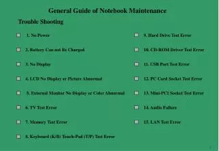
Module contents • ORiNOCO Software tools • Non ORiNOCO tools • Hardware indicators • Configurator error messages • Common problems • Rescue procedures
ORiNOCO ToolsORiNOCO Client Manager Opening screen (status window) • General indication of status • Channel • Link Quality • Speed • Communications between client station and RG has two phases: • Successful communication between the two radios (indicated by the Access Point name being the MAC address of the PC Card in the RG) • Successful association with the RG (indicated by Access Point name being a real RG name)
ORiNOCO ToolsORiNOCO Client Manager Link test • To diagnose communications path between station and RG • SNR (Signal to Noise ratio) • SNR is the most important communications quality indicator • Low SNR not always means loss of of the link; may result in lower performance • RG should be positioned in such a way that stations have acceptable to good SNR at all places in the network
ORiNOCO ToolsORiNOCO Client Manager Link test (cont’d) • Noise level • Interference sources show themselves as noise, so observe noise level • Packet loss counter • Sometimes low SNR does not directly cause packets to be lost therefore loss of packets is sometimes a better indicator of the quality of the link • Bit-rate counter • When auto-rate select is configured, station might fall back to lower speed when SNR drops
ORiNOCO ToolsORiNOCO Client Manager History • shows selected characteristic over time. • Allows “spikes” to be observed in noise level • Mark spots with high noise level and increase reconfigure the RG-1000 accordingly: • Change channel • Reposition the RG-1000
ORiNOCO ToolsORiNOCO System Tray indicators RF Link Indicator • Shows status of link to RG by color (and number and height of bars) • Allows activation of ORiNOCO Client Manager, Network Status window and Diagnose Card RG profile manager’ modem indicator • Works in combination with the RG-1000 • Shows status of built-in modem • Green lights and receiver lifted: connected • Flashing lights with receiver lifted: dialing • Receiver on hook: no phone connection RF link Indicator Modem Status Indicator
ORiNOCO ToolsDetermining version level of SW/FW Client SW/FW: • Use Client Manager Help function and select “Version Info” • The “Version Info” window will show version level of: • Client Manager • Client Driver • PC Card Hardware • PC Card Primary Firmware • PC Card Station Firmware (I.e. the IEEE 802.11 MAC implementation)
ORiNOCO ToolsRG Profile Manager (RG-1000) • Right-click on the “phone” icon pops up the menu • Under help additional diagnostic options are present: Version information • Version level of the Profile Manager • Version level and Serial number of the RG-1000 • Needed to determine when to upgrade Modem log • Display of most recent modem log (syslog messages • Helps determine at what point connection failure has occurred (if any)
ORiNOCO ToolsORiNOCO Set-up Utility Final set-up screen • Shows initial modem sequence • Initialization of modem • Modem Dialing • PPP protocol stack connection status • Failure in any of these steps is indicated
ORiNOCO ToolsDetermining version level of SW/FW RG (and setup utility): • Press F12 when the RG-Setup utility has started and the configuration data has been obtained from the RG • The version info window displays revision levels of: • Setup Utility itself • SW in the RG (I.e. the bin file or image) • RG Hardware • Version of the built-in modem (RG-1000 only) • MAC address of the the Ethernet port inside the RG • Version of JRE
ORiNOCO ToolsUpgrading the software inside the RG Upgrading the bin file: • At start up of the SW, the RG setup utility compares the version level of the SW inside the RG with the version that came with the utility (or a later version that has been placed in the subdirectory of the utility) • When a newer version is present the user is prompted to let the setup utility upgrade the RG before any other activity can take place.
ORiNOCO ToolsAP Manager - entering password • To access an RG for monitoring, an Read password has to be supplied: • Default password is “public” • Each time the Set-up utility (previous slides) is used when password is “public” the default password is changed to the RG identification (e.g. 23cc38) • Clicking monitor and entering the correct read password, will spawn the monitoring window
ORiNOCO ToolsAP Manager - monitoring options Monitoring tallies • System windows • Version info • Remote link test • Bridge Learn table • shows all learned MAC addresses and their port • IP ARP table • Match-up between IP address and MAC address • Several tally windows
ORiNOCO ToolsAP Manager - Remote Link Test Remote Link test • Activated from AP manager • Shows all associated stations • Link test can be conducted from RG to selected associated station • SNR • Signal • Noise • Packet loss counter
ORiNOCO ToolsAP Manager - Interface tallies Interface tallies • Select one of the available interfaces: • Wired • Wireless • Modem (RG-1000) • For each of the interfaces several statistics are kept: • In/Out errors • In/Out packets • etc… • Screen can be printed for later analysis
Non-ORiNOCO Software ToolsTCP/IP “PING” TCP/IP “Ping” • A test command run from a DOS prompt within Win ‘95 or WinNT using TCP/IP protocol stack. • Tests that minimal network connectivity from transport layer to transport layer exists • Endpoint IP address can be any where in Network, testing across bridge/routers • Sometimes part of package with IP tools (e.g. WS Ping ProPack)
Non-ORiNOCO Software ToolsIP Configuration tool Winipcfg (Windows 95/98) • Standard tool showing IP settings • “Release” and “renew” of IP lease • May be needed when mobile client switches between different networks (home vs office), where different IP address ranges apply • “IP Config” to provide information about IP settings • c:\windows\winipcfg.exe - for WIN’95 • c:\windows\ipcfg.exe - for WIN3.11 • c:\winnt\….\ipconfig.exe - for WINNT 3.5-4.0
Non-ORiNOCO Software ToolsLAN Analyzers / sniffers • Provide data capture capability (sniffer function) • Have protocol decoding capability • Can be used to trap on selected devices to isolate errors • Have logging capability • Examples: • LANWatch - FTP Software, Inc. (DOS based) • Sniffer - Network Associates (Windows based)
Non-ORiNOCO Software ToolsSYSLOG message display tools • RG will issue “SYSLOG” messages on certain defined events • SYSLOG messages can be used to trace steps when error situations occur • SYSLOG messages are broadcast messages that can be received by “Daemon” applications for display (shareware tools) • e.g. Kiwi’s SYSLOG Daemon
Power LED On when power is applied Wireless LED Flashes on wireless activity Ethernet LED Flashes on wired activity Modem LED Flashes on modem activity Hardware indicators RG LEDs • Generic LED definitions: • Specific events or conditions are reflected by LED sequences and/or LED colors
Hardware indicators RG Power LED Off • Device is not powered on • When power adapter is inserted and cables connected: • Broken RG • Failing Power supply • Broken cables Red • General Hardware Failure • If one of he other LEDs is Orange, it reflects hardware failure on that port
Hardware indicators RG Power LED (cont’d) Green • Device is operational • Other LEDs flashing or off Orange • Indicates special mode (will return to normal mode within a minute): • After supplying power to the unit (powering up) • After finishing the RG setup utility • After pressing the Reset button • After pressing the Reload button
Hardware indicators RG Wireless LED (Power LED is green) Flashing Green • The RG receives or sends data from/to its wireless network Off • The RG does not receive or send data from/to its wireless network Flashing Red • The RG tries to send data to the wireless network but fails
Hardware indicators RG Wired LED (Power LED is green) Flashing Green • The RG receives or sends data from/to its wired network Off • The RG does not receive or send data from/to its wired network Flashing Red • The RGtries to send data to the wired network but fails
Hardware indicators RG-1000 modem LED (Power LED is green) Flashing Green • The RG-1000 receives or sends data from/to the telephone line Off • The RG-1000 does not receive or send data from/to the telephone line Flashing Red • The RG-1000 tries to send data to the telephone line but fails
Hardware indicators Special sequences Power on sequence • All four LEDs orange (4 seconds) • Power LED red (7 seconds) • Wireless LED orange (1 second) • All LEDs off (3 seconds) • Power LED green • Rapid orange flashes on Wireless and wired LEDs
Hardware indicators Special sequences Upload FW sequence • during SW transfer Power LED green and Wireless LED green (if upload from wireless terminal) • Power LED Orange • Several instances of a sequence of RED flashes: Power, Wired, Wireless, Modem (in that order) • Power LED green • Rapid orange flashes on Wireless and wired LEDs
Hardware indicatorsORiNOCO PC Card • Power LED (b) • LED is on when station has association with an RG • In power save mode this LED flashes with app. same frequency as beacon messages (default 10 per second) • When power LED is off it means that the station has no association with an RG • Traffic indicator (a) • This LED lights up when data is sent or received
Configurator error messagesSome frequently occurring messages “Cannot find your ORiNOCO RG” • No physical connection present between the configurator station and the RG. Could be: • Incorrect cable when using wired connection • Incorrect ID entered as network name in the client driver settings when using wireless connection • Incorrect setting of encryption key in the client driver settings when using wireless connection
Configurator error messagesSome frequently occurring messages “An ORiNOCO RG found, but cannot read its current settings. Please try again (select continue)” • No logical connection present between the configurator station and the RG. Could be: • IP address of configurator and RG not in the same sub-net • Can be solved by: • Obtaining new IP address from RG • Assigning static IP address to configurator in same sub-net of RG • List of error messages and explanation present in manual and help files
Common ProblemsInability to connect to the RG • Check the physical connection by “PING-ing” the RG • Failing PING could be caused by: • Incorrect IP address setting on configurator station • Failure in the physical media (cable, wireless) • To fix check the following and correct if needed: • For wireless connection • The setting of the client driver mode (should not be IBSS or AP mode) • Network name = RG ID. (If the PC card has been changed, the ID changes, which may not have been shown on the label) • The setting for the encryption key • Failure in the wired setting could mean incorrect cable or hub
Common ProblemsInability to get configuration from the RG • Physical connection has been verified, but configurator cannot load the configuration data • Failing to obtain configuration data could be caused by: • Incorrect IP address setting on configurator station in relation to that of the RG • Failure in RG itself (no response, frequent reboot) • To fix incorrect IP settings: • Verify setting using IPConfig • Release and renew IP lease • Failure in RG itself may require a new software load module (see rescue procedures
Common ProblemsLower than expected performance • System performance as perceived by user can be less than expected in terms of: • Station-to-station throughput • Internet access response times • If wireless station-to-station throughput is measured (file transfer) as less than 1.5 Mbps, at relative short distance of the stations to the RG, it could mean that: • Interference source is present • Neighboring user uses similar channel • To fix: • Use Client Manager to find source of interference and change channel. • Deploy RG away from source of interference. • If Internet responses are slow it often is caused by the Internet itself or the connection speed to the ISP.
Common ProblemsLess than expected range • The communication distance between a wireless client and the RG as perceived by user can be less than expected in terms of: • Inability to cover required areas within the residence • Lower throughput due to auto-rate fall back • Can be caused : • Presence of an interference source • Objects in the communication path that impact the wireless connection • To fix: • Use Client Manager to find source of interference and to determine the possible data-rate at different positions in the residence. • Deploy RG away from source of interference. • Reduce effect of RF barriers, changing position of RG and/or clients
Common ProblemsAssess the possible data-rate at given positions • Run ORiNOCO Client Manager and proceed to Link test • Observe the tally fields that count the received packets in relation to the data-rate • Move around the residence to determine the points where the data-rate changes • Drop in data-rate can be caused by interfering objects in the path
Common ProblemsLoss of communications • The communication between a wireless client and the RG is interrupted or completely lost • Can be caused : • Presence of an interference source • To fix: • Use ORiNOCO Client Manager to localize a potential source of interference • Remove the source of interference (if possible) • Deploy RG away from source of interference
Common problems Interference • Non-ORiNOCO device may be operational in the 2.4 GHz band and interfere with the Residential Wireless Network • RF interference may impact operation of the wireless network and is perceived by users as: • reduction in effective distance between Client station and the RG • Decrease of effective throughput (due to re-transmission) • How to handle? • Know the potential sources of interference • Localize the sources of interference • Remove or limit the source interference
Common problems Sources of interference • Other (home) devices that operate in the 2.4 GHz band: • Micro-wave ovens • 2.4 GHz Cordless Phones • Frequency Hopping neighbor networks • Neighboring ORiNOCO networks
Common problems Localize the sources of interference • Tools to use: • ORiNOCO Client Manager • Process to use: • Use a laptop to run ORiNOCO Client Manager • Show History test with signal and noise • Observe noise line and search for increase noise levels • Move towards the Noise source to gauge the range of its effect
Common problems Address the source of interference • Re-tune the channel used in the RG • Stay clear from the source of interference (maintain proper “near/far” distances) • Reposition the RG to be as far away from the source of interference as practical • Shield the source of interference d2 d1 Errorless Performance: d1=2.1 X d2 Worst Oven d1= .6 X d2 Average Oven d1= .35 X d2 Best Case Oven
Rescue Procedures Reset • Reset switch at point B • To recover from a situation where the RG is in a deadlock • Performing a reset will stop all network communications (for a few minutes)
Rescue Procedures Soft Reload • In Soft Reload mode encryption key settings will return to its default settings and the password will be disabled. • The Soft Reload mode is active for only 5 minutes. If this period of time has expired the message "Resetting encryption and password failed" will be displayed and the RG returns to normal mode.
Rescue Procedures Soft Reload • Proceed as follows: • Exit the RG Setup Utility. • Press Reload Switch (switch A) for 1 second. The RG power led turns amber. • Disable the encryption setting on the ORiNOCO PC Card. • Restart the RG Setup Utility. The program automatically starts in Soft Reload mode. • Press Yes to proceed. The encryption key will return to its default settings and the password will be disabled. • Press or No to abort and reboot your RG to restart in normal mode.
Module summary • ORiNOCO Software tools • Non ORiNOCO tools • Hardware indicators • Configurator error messages • Common problems • Rescue procedures