Download
1 / 29
351 likes | 1.03k Views
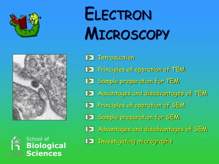
School of Biological Sciences. E LECTRON M ICROSCOPY. Introduction. Principles of operation of TEM. Sample preparation for TEM. Advantages and disadvantages of TEM. Principles of operation of SEM. Sample preparation for SEM. Advantages and disadvantages of SEM. Investigating micrographs.

E N D
School ofBiologicalSciences ELECTRONMICROSCOPY Introduction Principles of operation of TEM Sample preparation for TEM Advantages and disadvantages of TEM Principles of operation of SEM Sample preparation for SEM Advantages and disadvantages of SEM Investigating micrographs
INTRODUCTION With the invention of the light microscope it was discovered that plant and animal tissues were made up of aggregates of individual cells. However, light microscopes are limited to approximately x1000 magnification and have poorresolution. Therefore not all the internal structures of a cell can be seen with a light microscope. In 1924 a French physicist by the name of de Broglie stated that a beam of electrons should behave in a similar way to a beam of light i.e with wave properties the wavelength should be shorter. Therefore an electron beam should give better resolution.
RESOLUTION When there is sufficient light, two points 0.2mm apart or more can be distinguished with the naked eye as being separate points. When this distance is less than 0.2mm, only one point is seen. This distance is called the resolving power (or resolution) of the eye. In other words resolution is the closeness two objects can be in proximity and still be perceived as two separate objects. Can’t see two separate objects Can see two separate objects
Back to principles of operation The invention of the electron gun led to the development of the electron microscope. • The metal tungsten filament is heated to about 2500oC which causes it to release electrons. • Due to the large voltage difference between the filament and the anode plate the electrons are forced to flow in the direction of the arrow. • The cathode shield increases the electron flow further and concentrates the electrons into a narrow beam. Filament Cathode High voltage generator Electron beam Anode
TEM Transmission SEM Scanning Two main types of electron microscopes; TEM produces a high resolution image of the internal structures of cells. TEM uses the electrons that have passed through the specimen to form an image. SEM produces a three dimensional image of the specimen surface. A beam of electrons scans the whole specimen which then emits low energy, secondary electrons. This technique can be used to study whole cells.
When an electron beam strikes a specimen a number of events occur. Electrons are scattered depending on the nature of the material. If the electrons hit a dense array they are scattered out of the main beam and fewer electrons will reach the viewing screen. There is no fluorescence and that area appears dark. If the electrons pass a scarcity of atoms they travel straight through, hitting theviewing screen and causing fluorescence. That area will appear light. The image comes from the arrangement of light and dark patches on the screen.
Electron gun Specimen holder Projection chamber PRINCIPLES OF OPERATION OF TEM
The main components of a TEM are: e e Condenser lens e THE ELECTRON GUN – produces an electron beam. THE COLUMN – uses electromagnetic lenses to control the beam and produce a magnified image IMAGE VIEWING AND RECORDING The image is produced on a fluorescent screen below which a shutter and camera are located. e Specimen e Objective lens e e e Projector lens e e e e e e e e e e e e e e e Vacuum Fluorescent screen
Electrons only behave like light when they are manipulated in vacuum. Therefore the whole column is evacuated since atoms such as O2 and CO2 scatter the electrons. e e e e e e e
SAMPLE PREPARATION FOR TEM The aims of sample preparation are as follows: • To preserve the material in its natural state • To ensure that the material withstands changes which might occur on exposure to atmosphere, vacuum and electron beam.
Fixation for TEM The tissue is cut into tiny pieces It is then placed into fixing solution
Dehydration and embedding of TEM Tissue is placed in final embedding mixture and the resin is polymerised in the oven It is then placed in a dilute solution of resin embedding media Tissue is dehydrated in alcohol Specimen vials
3.05mm Section cutting of TEM The colour of the sections vary with thickness. When the sections are gold they are picked off the surface with a copper grid. Sections are cut on an ultramicrotome with a glass or diamond knife. The sections are floated off the edge of the knife onto the surface of a water trough. The section on the copper grid is now ready for staining and viewing in the electron microscope.
Thin sections are effectively two dimensional slices of tissue and do not convey the three dimensional arrangement of cellular components Advantages Disadvantages TEM • Very good resolution magnification • Artefacts may be created • Can see sub-cellular components and measure them
PRINCIPLES OF OPERATION OF SEM Electron gun Detector Detector Image viewing Specimen chamber Control panel
Electron source SEM uses electrons that are emitted from the specimen surface. The specimen is scanned with a very fine beam of electrons. These are scattered as they hit high and low points in the specimen. The scattered electrons are measured by a detector and used to control a second beam which forms an image on a TV screen T.V. Monitor e Electron beam e e e e e eee Specimen Detector Vacuum
Sample preparation for SEM The preservation used will usually determine which drying process to use. There are two basic methods of drying the specimen: • Freeze-drying – used after freezing • Critical point drying – used after chemical fixation and dehydration
…..placed in freeze drier Freeze drying for SEM Sample placed in nitrogen slush to maintain it’s structure Then placed in liquid nitrogen to allow easy handling Sample placed in copper holder and………. Sample is mounted on a stub
Sample is placed in critical point drier. Here the sample is flushed several times with liquid CO2. The pressure and temperature is then raised which converts the liquid CO2 to gas. The gas is then vented off slowly. Critical point drying for SEM Sample is chemically fixed Then dehydrated with alcohol The sample is removed and mounted on a stub
Coating the specimen for SEM Most biological specimens are poor conductors and poor emitters of secondary electrons therefore the surface of the sample needs to be coated with a thin layer of a conducting material. There are two ways to do this: • Sputter coating • Evaporation of carbon
METAL Sputter coating for SEM When power passes to the anode, the noble metal evaporates (called the plasma effect) and the metal falls onto and coats the specimen. ANODE A sputter coater CATHODE
CARBON RODS Evaporation of carbon for SEM Two carbon rods are placed end to end. One of the rods is sharpened to a point. These are placed in a vacuum and the specimen is placed below them. When electricity passes through the carbon rods, the carbon tip evaporates and the carbon falls onto and coats the specimen. CARBON RODS
Provides great depth of focus Micrographs show a 3D image of specimen Smaller and simpler in comparison to TEM Only surface features seen Resolution attainable is not very high (approx 10nmn) Advantages Disadvantages SEM
Investigating Micrographs Transmission Electron Micrographs Scanning Electron Micrographs Can you spot the differences between the two types of electron microscopy?
Virus particles Plasma membrane Endoplasmic reticulum Golgi membranes Mitochondrion Transmission Electron Micrographs Section of mammalian cell
Scanning Electron Micrographs Sample of geranium petal showing the cone shaped projections and the internal structure.
Measuring Micrographs How to work out the sizeof an organelle? Measured size Magnification Magnification of micrograph is X100000 Measured size = 80mm Convert to m = 80000 80000 m 100000 = 0.8m or 800nm
for using this programme. We hope that it has been useful! This programme was developed as part of a work placement project by Sumerah Khan and Sheerin Dariani THANKS TO: Chris Gilpin, Ian Miller Les Lockey, Samantha Newby
References • B. Schotanus (1980) Electron microscopy, what is it ? Marketing electron optics. Philips Export B.V. Eindhoven. • Dr Yvonne Miller (1998) Preparation of specimens for TEM and SEM. • Mike Mahon, Chris Gilipin, Ian Miller (2000) Microscopy and analysis University of Manchester - School of Biological Sciences. • Sam Newby (2000) Freeze drying and critical point drying EMPGU. • 5) Specimen preparation (1991) (21/1/00) http://www.lifelong.com/lifelong-universe/Academic world/SEM/ specimenprep.html pages 1-2. • 6) Dr. Ron Butler (1980) Transmission electron microscopy, What an SEM is ?, Aims of specimen preparation and Electron microscopy unit. EMPGU