Download
1 / 6
60 likes | 150 Views
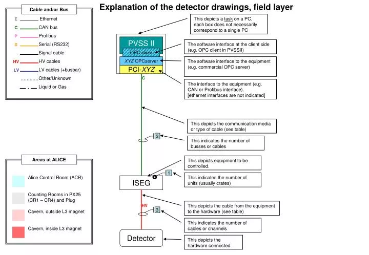
Explanation of the detector drawings, field layer. 1. 3. 3. Cable and/or Bus. Ethernet. This depicts a task on a PC, each box does not necessarily correspond to a single PC. E. CAN bus. C. Profibus. P. PVSS II. Serial (RS232).

E N D
Explanation of the detector drawings, field layer 1 3 3 Cable and/or Bus Ethernet This depicts a task on a PC, each box does not necessarily correspond to a single PC E CAN bus C Profibus P PVSS II Serial (RS232) The software interface at the client side (e.g. OPC client in PVSSII) S Signal cable OPC client HV cables XYZ OPCserver The software interface to the equipment (e.g. commercial OPC server) HV LV cables (+busbar) PCI-XYZ LV Other/Unknown C The interface to the equipment (e.g. CAN or Profibus interface). [ethernet interfaces are not indicated] Liquid or Gas This depicts the communication media or type of cable (see table) This indicates the number of busses or cables Areas at ALICE This depicts equipment to be controlled. Alice Control Room (ACR) Counting Rooms in PX25 (CR1 – CR4) and Plug Cavern, outside L3 magnet Cavern, inside L3 magnet This indicates the number of units (usually crates) ISEG HV This depicts the cable from the equipment to the hardware (see table) This indicates the number of cables or channels Detector This depicts the hardware connected
“Generic” architecture for the DCS “back end” User interface; main console for detector operation This depicts a task on one or more PC’s, there is no one-to-one correspondence between boxes and PC’s Main PVSS tasks; interface to field layer, Finite State Machine, … Database tasks (reading and writing). [FSM?] Database(s) PVSS II PVSS II PVSS II OPCclient DIMclient User interface Ethernet PVSS II PVSS II OPC client OPC client CAEN OPCserver Wiener OPCserver DIMserver SchneiderOPCserver Field layer, with field layer processes
V0 28/02/03 1 4 ? ? ? 156 [FSM?] Database(s) PVSS II Control room (ACR) PVSS II PVSS II OPCclient DIMclient User interface Ethernet PVSS II PVSS II OPC client OPC client CAEN OPC server DIMserver ? Wiener OPCserver PCI-CAN E C CAEN HV Front Endelectronics VME(wiener?) PMT Optical fibers Detector High Voltage FEE Crate Control
V0 (no URD) • High Voltage • Power supplies : CAEN SY1527 (13 boards A1733N) 1500 – 2000V, 156 channels (144 in use + 12 spares) • HV cable : 156 cables : type SHV Cables do not enter the magnet ; PMT located in the same rack that the HV supply. • FEE • Control discriminators setup and delay ⇒ ~ 900 parameters • Access through a VME master ? • Crate/Equipment Control (?) • VME crates - exact number and type to be decided • Any other system (calibration, alignment, …)? • Calibration using LED or laser (system and procedure to be defined) • Racks : • 2 racks have been allocated (one at each side of magnet) : see C. Gregory • Optical fibers path inside the magnet : • 4 rails of fibers (section of 50 x 30 mm each) for each side : see C. Gregory for exact path
V0 - Front End Electronics • Control of the discriminators (threshold and width) • Control of various delays • Choice between different trigger configurations (pp or AA channels) ⇒ ~ 900 parameters x 2 x 12 x 144 x 2 x 144 x 2