Download
1 / 9
160 likes | 558 Views
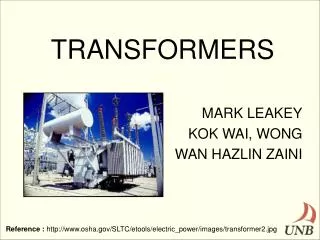
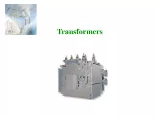
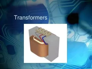
Chapter 11 Special Transformers. Dual-voltage distribution transformer. Transformers that supply electric power to residential areas generally have two secondary windings, each rated at 120 V.

E N D
Chapter 11 Special Transformers Electro Mechanical System
Dual-voltage distribution transformer • Transformers that supply electric power to residential areas generally have two secondary windings, each rated at 120 V. • The windings are connected in series, and so the total voltage between the lines is 240 V while that between the lines and the center tap is 120 V. The center tap, called neutral, is always connected to ground. • These kind of transformers are still used in industry where two voltages are required. Electro Mechanical System
Autotransformer • On some occasions it is desirable to change voltage levels by small amount • For example, it may be necessary to increase a voltage from 110 to 120 V or from 13.2 to 13.8 kV. • These small rises may be made necessary by voltage drops that occur in power systems a long way from the generators. • In such circumstances, it is wasteful and excessively expensive to wind a transformer with two full windings, each rated at about the same voltage. • A special-purpose transformer, called an autotransformer, is used instead for such increase/decrease. Electro Mechanical System
Autotransformer • When we connect load at output CA • I2 immediately causes I1 to flow • BC will carry current I1 and CA will carry current I2 – I1 • The mmf due to I1 must be equal to mmf due I2 – I1 • Which can be further reduced to • Neglecting transformer losses and excitation current .Power drawn by the load must be equal to supplied power Home Work: Page 227 Example 11-1 Electro Mechanical System
Conventional transformer as Autotransformer • Conventional two-winding transformer can be converted into autotransformer by connecting primary and secondary windings in series following rules apply: • Currents should not exceed nominal rating • Voltages should not exceed nominal rating • If rated current flows in one winding rated current automatically flows in other winding (ampere-turn ratio of the windings are always equal) • If rated voltages exists in one winding rated voltage automatically appears across other winding (ampere-turn ratio of the windings are always equal) • If current in one winding flows from H1 to H2, current in other winding should flow from X2 to X1 • Voltages add with opposite polarity (H1 & X2, or H2 & X1) and subtracts with same polarity (H1 & X1, or H2 & X2) Electro Mechanical System
Example • A standard single phase transformer 15kVA, 600V/120V,60Hz Connect it as autotransformer to obtain following voltages • 600 V primary to 480 V secondary • 600 V primary to 720 V secondary • 120 V primary to 480 V secondary • Also calculate maximum load in each case Nominal current of 600 V winding is I1 = S/E1 = 15000/600 = 25 A Nominal current of 600 V winding is I2 = S/E2 = 15000/120 = 125 A a) For 480 V, secondary 120 V must subtract from primary voltage 600. to obtain we must connect same polarity together. Electro Mechanical System
Example….cnt. current in 120 V winding is the same as that of load i.e nominal current rating of 125 A. Max. power drawn by the load is: Sa = 125 A x 480 V = 60 kVA Current 125 A flows from X1 to X2. Current 25 A must flows from H2 to H1 Leaving 100 A to flow from the source Power supplied by the source is: S = 100 A x 600 V = 60 kVA Electro Mechanical System
Example….cnt. b) For 600 V/720 V, secondary 120 V must be added to the primary voltage 600. to obtain we must connect opposite polarity together (H1 and X2) Current in secondary is same 125 A Max. power drawn by the load is: Sb = 125 A x 720 V = 90 kVA Autotransfarmer can supply a load of far greater capacity than original transformer c) For 120V/480V, same connections as solution In part a, source at X1 & X2 Load current cannot exceed 25 A Max. power drawn by the load is: Sc = 25 A x 480 V = 12 kVA Electro Mechanical System
Voltage transformers • Measure/Monitor the voltage on a transmission line • Isolate metering equipment from the line • High-precision transformers in which the ratio of primary to secondary current is a known constant. • Secondary voltage is in phase with the primary voltage. • Rated secondary voltage is usually 115 irrespective of what the rated primary voltage may be • Similar to conventional transformers, the insulation must be to withstand full line voltage on HV side Electro Mechanical System