Download
1 / 34
340 likes | 429 Views
BLS-to-ADF Transition System. Existing and proposed calorimeter trigger rack layouts. The color code shows how the calorimeter trigger inputs will be reassigned from the existing trigger crates to the new ADF crates. 100 mV/div 200 ns/div. 230 ns. Patch Panel.

E N D
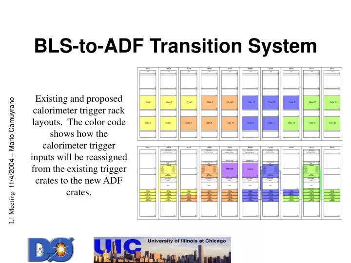
BLS-to-ADF Transition System Existing and proposed calorimeter trigger rack layouts. The color code shows how the calorimeter trigger inputs will be reassigned from the existing trigger crates to the new ADF crates. 100 mV/div 200 ns/div 230 ns
Patch Panel Paddle Card2 Pleated Foil Cables input from the Patch Panel Card ERNI connector output to the ADF backplane 3M Pleated Foil Cables Patch Panel Card (2 per Patch Panel)16 BLS inputs2 Pleated Foil Cables output to the Paddle Card) Design made by John Foglesong
6.5‘‘ Current BLS Cables Layout • How the BLS cables are set. Rack Door We decided to do not move the cables
PPC layout Design • Patch Panel Card shift 4’’ out to the rack to keep the cables coming from the front. PFC Front BLS Rack Front view Side view by John Foglesong
BLS Cables layout We are looked for the best Patch Panel location considering we need enough space to feet the ADF crates on racks M104 M106 M109 M111 and also TAB/GAB on crate M107 and Control on rack M108. We estimate around 17U
Mock-up We reproduce the current BLS cable layout for 128 BLS cables to test the design and to optimize the procedure to connect the cables
Mock-up 32 BLS cables rearranged For the bottom Patch Panel Crate.
Signal and Impedance Matching Tests A pulse was sent trough a BLS spare cable + Patch Panel Card + Pleated Foil Cable + Paddle Card. BLS Cable Zo ~ 80 Ω 3M Pleated Foil Cable Zo ~ 72 Ω R1 = 120.5 +/- 0.3 Ω R2 = 0 R3 = 72.0 +/- 0.3 Ω
Signal test Today R2 = 0 R3 = 500 Ohm Pick-Off pins R2 3M PFC Patch Panel Card + Paddle Card R2
Signal Test Connections: BLS Cable, Patch Panel Card, Pleated Foil Cable, Paddle Card
Signal Test • Connections:
Signal Test Input of the BLS cables bare signal Input 694 +/- 2 mV 50.0 ns 2.0 µs
Signal Test BLS Cable: Signal BLS Cable R1 R2 R1 = 112.9 +/- 0.3 Ω R2 = 76.6 +/- 0.3 Ω To match the signal generator 50 Ω then BLS DC Resistance ~ 13 Ω
Signal Test R1 = 107.5 +/- 0.3 Ω R2 = 7.4 +/- 0.3 Ω R3 = 71.0 +/- 0.3Ω R3 = 106 +/- 1Ω R3 = 51 +/- 1Ω
Signal Test R1 = 119.8 +/- 0.3 Ω R3 = 71.5 +/- 0.3 Ω R2 = 0 Ω
Signal Test R2 = 0 Attenuation:
Signal Test R2 = 0 Attenuation:
Signal Test R2 = 0
Signal Test R2 = 0
Signal Test R2 = 0
Signal Test R1 = 110.3 +/- 0.3 Ω R3 = 71.1 +/- 0.3 Ω R2 = 5.0 +/- 0.3 Ω
Signal Test R2 = 5.0 +/- 0.3 Ω Attenuation
Signal Test R2 = 5.0 +/- 0.3 Ω Attenuation
Signal Test R2 = 5.0 +/- 0.3 Ω
Signal Test R2 = 5.0 +/- 0.3 Ω
Signal Test R2 = 5.0 +/- 0.3 Ω
Signal Test R1 = 107.5 +/- 0.3 Ω R2 = 7.4 +/- 0.3 Ω R2 = 7.4 +/- 0.3 Ω
Signal Test R2 = 7.4 +/- 0.3 Ω Attenuation
Signal Test R2 = 7.4 +/- 0.3 Ω Attenuation
Signal Test R2 =7.4 +/- 0.3 Ω
Signal Test R2 =7.4 +/- 0.3 Ω
Signal Test R2 =7.4 +/- 0.3 Ω
Summary • Mock-up • The cable flow worked. • A procedure to handle the cables is being writing down. • Signal integrity coming out of the Patch Panel • There is a small difference on the impedance of the Pleated Foil Cable and the BLS Cable (order of magnitude 10 Ω) • If we add a resistance of this value in the Patch Panel the output decrease ~10% but it gets a little bit “cleaner”.