Download

1 / 87
880 likes | 1.08k Views
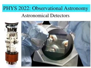
PHYS362 – Advanced Observational Astronomy. Professor David Carter. Slide set 4. Electronic Imaging Text Books. Astrophysical techniques – C.R. Kitchen: IOP Publishing. ISBN 0 7503 0498 7. Electronic Imaging in Astronomy – I.S. McLean: Wiley-Praxis. ISBN 0 471 96972 9.

E N D
PHYS362 – Advanced Observational Astronomy Professor David Carter Slide set 4
Electronic Imaging Text Books • Astrophysical techniques – C.R. Kitchen:IOP Publishing. ISBN 0 7503 0498 7. • Electronic Imaging in Astronomy – I.S. McLean: Wiley-Praxis. ISBN 0 471 96972 9.
Definitions for photon sensitive detectors • Responsive Quantum Efficiency (RQE) – Ratio of the number of detected photons to the number of incident photons. • Detective Quantum Efficiency – Square of the ratio of the output signal-to-noise ratio to the input signal-to-noise ratio • DQE is always less than or equal to the RQE because of the effect of noise.
Charge Coupled Device (CCD) detectors • Ubiquitous in optical and very near infra-red astronomy • The detector of choice at wavelengths from 400 nm to 1μm. • Available comparatively cheaply in very large pixel formats (a 2048 x 4096 array will cost around £40,000). • Robust enough to fly on space missions.
Principles of the CCD • In a solid crystal electrons in the uppermost orbits of atoms, the valence electrons,interact to bind the atoms together. • The energy levels are shared between atoms, are split by small amounts. With a crystal with millions of atoms, the levels are spread out into a band. • Higher levels are split also
Principles of the CCD • The lowest band is filled with electrons because there is one electron for each atom. This is called the valence band. • The next level up is empty, and is called the conduction band. If electrons do get into this they are free to move between atoms. • Between the valence band and the conduction band is a forbidden energy gap or band gap.
Principles of the CCD • In a conductor the valence band and conduction bands overlap, allowing electrons to move freely between the two. • In an insulator there is a large forbidden energy gap, so electrons can’t get into the conduction band to conduct electricity • In a semiconductor there is a small forbidden energy gap, so some electrons can move into the conduction bands. • If an electron moves into the conduction band, because of thermal effects or interaction with a photon, it leaves a hole in the valence band, so an electron-hole pair is created
Semiconductors Part of the periodic table. Semiconductors are in column IV of this table (e.g. Silicon, Germanium) or compounds of III-V (e.g. Indium Antimonide) or occasionally II-VI (e.g. Mercury Cadmium Telluride) elements.
Semiconductor band gap Band gap EG and corresponding critical wavelength λc for various semiconductors. The silicon band gap is less than then energy of optical photons. InSb and HgCdTe are used in infra-red applications. Band gap is temperature dependent.
The Charge Coupled Device • A CCD is a silicon wafer which is exposed to radiation. • The picture elements (pixels) of the CCD are defined by the electrode structure which is applied to this wafer.
Principles of the CCD • A series of electrodes is then placed above the surface of the silicon, separated from the silicon by a thin silicon dioxide insulating layer. A positive voltage is applied to the electrode , which then attracts and stores the electrons generated beneath this electrode
Principles of the CCD • As you expose the CCD to radiation, electron- hole pairs are generated and the electrons build up in the electron storage areas immediately below the positive potential electrodes. • After a while (seconds to minutes) the CCD contains an electrostatic representation of the pattern of incident radiation on it. • This somehow must be read out and stored in digital form.
Principles of the CCD • CCD is made out of p-doped silicon. This has excess holes compared with pairs. Holes are driven away from the positive potential, so a depletion layer is formed under the electrode. This is the collection phase. Regions away from the electrode or under electrodes at lower positive potential have excess holes, and form an insulating layer. This is the barrier phase
CCD readout 3 phase CCD design. Each picture element (pixel) has 3 electrodes. During exposure the centre of the three is held at positive voltage (about +10 V) and the charge builds up under this. Then the shutter is closed, and the voltage on the electrode to the right ramps up to +10V as that on thecentre one ramps down. The charge shifts to under the right electrode. Repeat twice more, and the charge has moved one whole pixel.
CCD readout • CCD is a two dimensional device. After the shutter is closed, the entire image is shifted down by one pixel, the bottom pixel is shifted into a horizontal readout register. • The readout register is shifted to the right by one pixel, and the pixel at the bottom right is shifted into a readout capacitor. • The charge causes an instantaneous change V=Q/C in the voltage of the input line of the on-chip transistor, which in turn causes a change in voltage on the input line • The voltage change is then amplified and digitised. • The storage capacitor is then reset.
CCD readout • This process is then repeated until each pixel in the readout register has been digitised. • The image is then shifted down vertically by one more pixel, the next row is shifted into the readout register, and this is digitised in the same way. • The whole process is repeated until the entire image is read out. • For a 2048 x 2048 pixel CCD it takes approximately 10 seconds to read out the whole chip. • A CCD read out this way is a line transfer CCD.
CCD readout • The channel stops between columns are permanent as charge does not move horizontally except in the readout register. • These channel stops are biased to negative potential by doping, hence charge cannot leak horizontally.
Buried channel CCD • CCDs described before are surface channel CCDs, but in these the charge is being shifted along in a thin layer just below the oxide insulator. • Surface layer has crystal irregularities which can trap charge, causing loss of charge and image smear. • If there is a layer of n-doped silicon above the p-doped layer, and a voltage bias is applied between the layers, the storage region will be deep within the depletion region • This is called a buried-channel CCD, and suffers much less from charge trapping.
Buried channel CCD A single pixel in a buried channel CCD
Thinned back-illuminated CCD • As described to now, the CCDs are illuminated through the electrodes. Electrodes are semi-transparent, but some losses occur, and they are non-uniform losses, so the sensitivity will vary within one pixel. • Solution is to thin the CCD, either by mechanical machining or chemical etching, to about 10μm, and mount it the other way up, so the light reaches it from the back.
Thinned back-illuminated CCD Thinned back illuminated (left) and thick virtual phase (right) CCDs
Frame transfer CCDs • Instead of reading the CCD out line by line as described before, a Frame transfer CCD has half of its area masked off to stop light reaching it. On readout, the whole CCD is clocked vertically so that the image area is transferred to the storage area. • The image can then be read out from this storage area whilst the image area is being exposed again.
Dark Current • Dark current is generated when thermal effects cause an electron to move from the valence band to the conduction band. • The majority of dark current is created near the interface between the Si and the SiO2, where interface states at energy between the valence and conduction bands act as a stepping stone for electrons. • CCDs are operated at temperatures of around 140K, to reduce thermal effects.
Dark Current • Multi-Phase Pinned (MPP) CCDs are doped with boron to allow the gate potentials to be positive with respect to the substrate, which causes holes to migrate to the surface area where they fill up these interface states. • This has the effect of reducing dark current, and MPP CCDs can be run at much higher temperatures than non-MPP CCDs. • Dark current at 140K is typically 10-4 electrons/s/pixel, i.e. negligible.
Linearity and Saturation • CCD pixels have a linear response of measured output voltage to a value quite close to the full well capacity of the pixel. The number of electrons which can be stored is given by: Q = CV/e V is the voltage, and C is the capacitance of the pixel, given approximately by: C Aκε0/d A is the area of the pixel, d is the thickness of the SiO2 layer, κ is the dielectric constant of SiO2 (about 4.5) and ε0 is the permittivity of free space.
Linearity and Saturation • Typically the full well capacity of a CCD pixel 25 μm square is 500,000 electrons. If the charge in the well exceeds about 80% of this value the response will be non-linear. If it exceeds this value charge will spread through the barrier phase to surrounding pixels. • This charge bleeding occurs mainly vertically, as there is little horizontal bleeding because of the permanent doped channel stops. • Readout register pixels are larger, so there is less saturation effect in the readout register.
Cosmic rays, X-rays, and particle radiation • There are a number of types of radiation which can interact with the silicon to produce several tens of electron-hole pairs in a cluster, which appears as a bright spot (if the radiation is normal to the detector) or a streak if it is steeply inclined. These radiation events are: • Secondary muons in cosmic ray air showers. • X rays emitted by UV transmitting glass in the optics of the instrument. • Radioactivity from heavy metal impurities in the cryostats. • These events are identified, classified and rejected by splitting the CCD exposure into two or more equal parts, the hits don’t occur in the same place.
Charge Transfer Efficiency • When the wells are nearly empty, charge can be trapped by impurities in the silicon. So faint images can have tails in the vertical direction. • Modern CCDs can have a charge transfer efficiency per transfer of 0.9999995, so after 2000 transfers only 0.1% of the charge is lost.
CCD readout noise • CCDs suffer from readout noise which has a variety of sources: • The output Field Effect Transistor. This is the ulitimate limit to the readout noise, at a level of 2-3 electrons. • Transfer loss fluctuations. During transfer an amount of charge is left behind, but this amount varies. Transfer noise is given by: σtr= (2ζnN0) where ζ = 1-CTE is the fraction of charge not transferred, n is the number of transfers and N0 is the original charge. For faint sources (100 electrons) this noise is less than 1 electron.
CCD readout noise • Reset noise: there is a noise associated with recharging the output storage capacitor, given by σres= (kTC) / e where C is the output capacitance in Farads. This noise could dominate, but it is removed by Correlated Double Sampling, where the reset voltage is measured after reset and again after readout. The first value is subtracted from the second, as this voltage will not change. • Surface State noise, due to fast interface states which absorb and release charges on short timescales. This is given by σss= (2kTnρssA), where n is the number of transfers, ρss is the density of fast interface states, andA is the pixel area. In buried channel CCDs, ρss is very low and this source of noise is less than 1 electron.
Other noise sources • Fixed pattern noise. The sensitivity of pixels is not the same, for reasons such as differences in thickness, area of electrodes, doping. However these differences do not change, and can be calibrated out by dividing by a flat field, which is an exposure of a uniform light source. • Bias noise. The bias voltage applied to the substrate causes an offset in the signal, which can vary from pixel to pixel. This can be removed by subtracting the average of a number of bias frames, which are readouts of zero exposure frames. Modern CCDs rarely display any fixed pattern bias noise
Interference Fringes • In thinned CCDs there are interference effects caused by multiple reflections within the silicon layer, or within the resin which holds the CCD to a glass plate to flatten it. • These effects are classical thin film interference (Newton’s rings). • Only visible if there is strong line radiation in the passband, either in the object or in the sky background. • Visible in the sky at wavelengths > 700nm. • Corrected by subtracting off a scaled exposure of blank sky.
Other noise sources • Electronic Pickup. Electronic noise sources caused by ground loops, or pickup of Radio Frequency radiation by cables and wires in the system, often dominates over noise sources within the CCD itself. This noise is easy to see, it forms ripples in the background, particularly in bias frames, but it is not fixed pattern so it is not easy to remove.
CCDs and mosaics 4096 x 2048 3 edge buttable CCD Canada-France-Hawaii telescope 12k x8k mosaic
Signal to noise ratio (S/N) • Output S/N = Input S/N x (DQE) • To calculate the S/N of an observation we need to know the signal, and all sources of noise. These are: • Photon noise (shot noise from the signal). • Photon noise from the sky background under the signal. • Photon noise from the sky background measurement to be subtracted off. • Readout noise from all sources. • Electronic pickup noise. • Fixed pattern noise. • Bias noise • Dark current noise.
A case study of simple aperture photometry • We observe a star on a CCD detector, and process the data in the simplest way possible. • An area centred on the star is defined to be the object area, and is large enough to contain all of the photons from that star. • An equal area some distance away, which is found to be free of stars, is defined as the sky background area, and the sky background is measured from that.
A case study of simple aperture photometry • We will make some assumptions: • We have eliminated fixed pattern noise by dividing the image by a normalised long exposure of a uniform light source, this is called a flat field. • Electronic pickup noise is indistinguishable from readout noise, and is included in the value given for readout noise. • Bias noise and dark current noise are negligible, as this is a cryogenically cooled, buried channel, MPP CCD.
Aperture photometry • Pixels are xμm square which equates to y arcseconds on the sky. • Star is observed in a circular aperture of area αsquare arcseconds which covers npix pixels. • Sky background is determined from a circular aperture of the same size. • Readout/pickup noise is σR electrons. • Aperture of telescope is D metres • We observe a star of magnitude V in the visual (green) passband.
Standard photometric passbands Standard photometric passbands
Standard photometric passbands Johnson and Stromgren passbands
Signal calculation • We start from the number of photons incident upon the top of the atmosphere of the earth from this star • A star of V=0, observed at a wavelength of 500nm gives: 1.0 x 10⁸Δλ A photons/second In bands other than V the number which is 1.0 here is different, in bluer bands it is more, in redder bands less. incident upon the top of the atmosphere in photometric (clear) conditions Δλ is the filter passband in nm A is the telescope collecting area in metres2.
Signal calculation • Thats at the top of the atmosphere. There are a number of efficiency factors we need to multiply by to calculate the signal which reaches the detector: • Atmospheric transmission εatm (~0.88 for a star at the zenith). • Telescope reflection efficiency εtel (~0.92 per mirror = 0.846 for a Cassegrain telescope) • Filter transmission εfilt (~0.85 for a broadband filter) • CCD Responsive Quantum Efficiency εCCD (~0.75) • Cryostat entrance window efficiency εwin (~0.95)