Download
1 / 19
190 likes | 288 Views
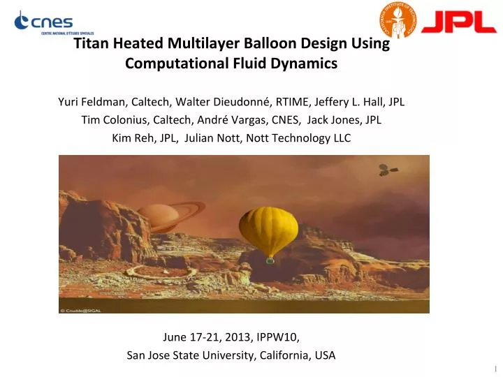
Titan Heated Multilayer Balloon Design Using Computational Fluid Dynamics Yuri Feldman, Caltech, Walter Dieudonné , RTIME , Jeffery L. Hall, JPL Tim Colonius, Caltech, André Vargas, CNES, Jack Jones, JPL Kim Reh, JPL, Julian Nott, Nott Technology LLC June 17-21, 2013, IPPW10,

E N D
Titan Heated Multilayer Balloon Design Using Computational Fluid Dynamics Yuri Feldman, Caltech, Walter Dieudonné, RTIME, Jeffery L. Hall, JPL Tim Colonius, Caltech, André Vargas, CNES, Jack Jones, JPL Kim Reh, JPL, Julian Nott, Nott Technology LLC June 17-21, 2013, IPPW10, San Jose State University, California, USA
Titan –Fascinating Planet • Titan, hosts chemistry similar to pre-biotic conditions on Earth. Hydrocarbon rivers, lakes and oceans. Titan is home for mountains reaching 2km in height and vast deserts filled with dunes. Titan is among very few places in the solar system where the surface is actively modified by flowing liquids. • It was recently concluded that Titan is likely hiding a global, sub-surface water ocean, 100 km beneath its surface with a great potential for existence of extraterrestrial life. www.universetoday.com
Titan MontgolfiereAerobot maximum2kW D≤18 m Titan: Cold (83 K), dense (3.6 kg/m3), low gravity (g=1.4 m/s2) Low temperature radiation unimportant compared to natural convection. 100 times less power than on Earth for comparable payload
Prediction methods • The JPL/Caltech and CNES/RTIME groups have used all four main prediction/estimation techniques for the Titan Montgolfiere Balloon: • Engineering correlations • Semi-analytical correlations for convective heat transfer around/between uniform temperature spheres • Reynolds-averaged Navier-Stokes (RANS) • Averages out and models all intrinsic turbulence space/time scales • Large-eddy Simulation (LES) • Spatially filter out/supply model for the small scales • Direct Numerical Simulation (DNS) • Directly resolve all scales • All require experimental validation (see next). Uncertainty Computational Expense
Cryogenic Balloon Tests Single wall balloon in chamber prior to test • JPL conducted cryogenic experiments on a two 1-meter diameter balloons at a Wyle Laboratories in April 2011. • The main purpose was to get data to validate the CFD models for single and double wall designs. • Both balloons had 4 thermocouples embedded in a gore. • The double wall balloon had a 5 cm gap and one transparent gore to enable verification of gap inflation. • Environment temperatures: 190, 140 and 90 K. • Heat input levels: 100, 250, 400, 550 and 700 Watts (not all levels used for each balloon and each thermal environment). • Load cell with 1.0 kg range used for measuring lift.
Experimental results • Good agreement between the experimental and simulation results. • Over predicted buoyancy values for the results based on engineering correlations. • The largest uncertainty is in the engineering correlation for heat transfer inside insulating gap.
Outline Investigation of the Montgolfiere thermal efficiency With gondola , different heat source and gondola locations Without gondola , optimized gap width and heat source location • Thermal efficiency analysis as a function of different heat source locations relativelyto the balloon mouth . • Influence of the gondola position on the balloon inflation rate during the deployment phase. Deriving modified heat transfer correlation for narrow spherical shell basing on detailed CFD analysis. System level analysis of the double- and multiple-walled balloon based on existing and modified heat transfer correlations.
Physical Characteristics Gravity force Buoyancy force (acting in the opposite to gravity force direction) Viscous forces (responsible for diffusion of momentum) Characteristic scales:
DNS Limit Ra =106 , f = 0.714, DNS 32x106 f.v., 1024 cores Slightly Supercritical -Turbulence Transition Step response for increasing Ra = 5x10⁴ to Ra = 106 Temperature X-Y section g
Full Scale Nu-Ra Functionality 103 ≤ Ra ≤ 109, Pr = 0.71 An excellent agreement between the average Nu values predicted by both LES and DNS For narrow shell and moderate Ra,Nu a Ra*0.3
Multiple-Walled Design, (I ) 10 m balloon, , Scanlan et al. 1970 presently derived Payload = Buoyancy - Own Balloon Weight, rfabric= 50 gr/m2
Multiple-Walled Design, (II ) Quadruple-walled Double-walled Triple-walled • Growth of payload with the number of gap layers. Payload prediction by employing presently derived gap correlation
RTG Location Varying RTG locations are considered in the context of increasing of operational flexibility (installation constraints, ascend/descend phases). The optimal RTG (heater) location within the balloon (close to the balloon mouth) has been set as a baseline for the future analysis. The location of RTG outside the balloon is investigated . Using CFD several external RTG locations are compared (in terms of buoyancy) for double-wall balloons (10m diameter, 20cm gap, 1m diameter of the balloon mouth).
Payload Versus RTG Location The payload values decrease when the RTG is moved away from the balloon mouth (on top of the gondola). The baseline value (internally placed RTG) exhibits the highest payload. The thermal field (right) exhibits an abrupt cooling for externally located heaters compared to the baseline heater location
Thermal Losses • The RTG is exposed to a cold flow: the RTG warms up the external atmosphere instead of warming up the internal flow. • The RTG plume flow spills at the inlet: not all the warm flow goes inside the balloon, some warm flow is diverted outside the balloon. • Warm internal flow (inside the envelope) is ejected outside the balloon with higher intensity : as a result of suction of external heated and overall mass conservation inside the balloon. The above flow ejection is also responsible for the flow spillage.
Deployment phase • Varying gondola distance (2 to 6m) during Titan initial deployment at 40km (without RTG). • 10m diameter balloon, 20cm gap, 1m inlet diameter. • Gondola wake / balloon inlet interaction: decrease inlet mass flow rate. • Inlet mass flow = inflation rate during initial deployment. • Baseline = no external gondola (only the viscous effects, without viscous effects the flow rate is 26,85 kg/s). • Due to the wake interaction with the inlet, the mass flow rate decreases substantially as the external gondola approaches the inlet.
Balloon filling An entire flight descent from 40km to ceiling altitude for a 200kg payload balloon with a 1740W heater is simulated with varying inlet mass flow rate efficiency factor (1.00 = ideal case, no perturbation at the inlet). During the first hour the balloon inflation is slowed down. However for the entire flight history: no noticeable effect due to poor inflation rates. System is robust to inlet flow perturbations due to the Titan’s small gravity
Conclusions An updated engineering correlation has been derived using LES and DNS to provide the Nusselt values as a function of Rayleigh and gap geometry. The newly derived correlation agrees with recent experiments and with standard RANS computations. CFD & system level studies using multilayer set-ups (2, 3, 4 walls) have demonstrated improvements in balloon performances for 4 walls balloons. Externally located heat source must be avoided due to its negative effect on the overall balloon buoyancy The external scientific gondola results in a substantial wake but has a small effect on balloon descent time
Nu-Ra Functionality, Small Ra Ra≤105, Pr=0.71 Scanlan(1970) Raithby & Hollands (1975) Teerstra et al. (2006) Ra*=Ra2L/Di Acceptable agreement for 0.5 ≤f ≤0.714 Poor agreement for the narrow , f ≥ 0.85 shells.