Download
1 / 25
250 likes | 428 Views
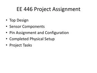
Senior Design Project: Interactive LED Array. By Khadijah Abdul Latiff Chong, Wee Siong. Contents. Introduction Initial Design Testing of Individual Components Explanation of Design Testing of Design Performance and Results Future Considerations. Introduction.

E N D
Senior Design Project:Interactive LED Array By Khadijah Abdul Latiff Chong, Wee Siong
Contents • Introduction • Initial Design • Testing of Individual Components • Explanation of Design • Testing of Design • Performance and Results • Future Considerations
Introduction • What is the motivation? • Where did the idea come from? • What are the functions? • What are the benefits?
Initial Design SENSORS Analog MUX Microcontroller circuit User control LED Driver LED Array
Testing of Individual Components Critical components in design • Color sensor • Tri-color LEDs • LED Driver • PIC Microcontroller
Testing of Individual Components Color sensor Avago Technologies • Responsivity of sensor • Testing conditions: • Ambient light • Type of object • Distance from sensor
Design and Fabrication Color sensor circuit • White LED • Black cover to absorb ambient light • Follow application notes • Noise reduction using bypass capacitor 0.1F
Design and Fabrication LED array • Simulate ON/OFF • Simulate PWM
Design and Fabrication SENSORS PIC microcontroller • Run test program • I2C protocol Analog MUX User control Microcontroller circuit I2C LED Driver LED Array
Solutions • PIC Microcontroller (Different Algorithms) • Analog Circuit
Analog replicating circuit Non inverting Op Amp Color Sensor Non inverting Op Amp Non inverting Op Amp Tri Color LED *op amp to manually calibrate color accuracy
Gain Adjustment Trial and error method
The color accuracy test • The orange test • Measure with another color sensor • Performance within 10% • Color sensors may vary in response
PROS Intensity Unlimited spectrum No PIC required CONS Trial and error Limited resistor values Require amplification for every signal Larger circuit Even larger circuit is needed to integrate a contrast function Analog replicating circuit
Color LED Panel • Gradient color as object move across sensors
Solution 2: PIC Microcontroller • Performs both replicate and complement functions. Color sensor Tri-color LEDs PIC
Replicate: RED 2: 1 2: 1 1: 2 1: 2 blue Green 2: 1 1: 2
1) DC Power Supply PIC Multimeter Tri-color LED 2) PIC DC Power Supply Multimeter 3) Color sensor PIC Tri-color LED
Results • Vred > 0.5* Vblue && Vred > 0.5*Vgreen -- output red • Vblue> 0.5* Vred && Vblue >0.5* Vgreen - output blue • Vgreen > 0.5* Vred && Vgreen > 0.5*Vblue - output green Replicate Function was chosen: Vout from sensor: Conditions checking: Observation: • Vred: 0.23 V output red RED • Vblue: 0.105 V do not output blue • Vgreen: 0.075V do not output green
Results Complement Function was chosen: Vout from sensor: Conditions checking: Observation: • Vred: 0.23 V do not output red Blue+Green • Vblue: 0.105 V output blue • Vgreen: 0.075V output green
Comparisons Analog circuit PIC microcontroller 1) Control of intensity 1) Less components 2) Higher Accuracy 2) Better Performance under room environment 3) Replicate Less colors
Using the PWM Module Analog DeMux sensors LEDs Analog Mux LED Driver Circuit PIC (15 Signals)
Future considerations • Get I2C protocol to work between PIC and LED driver • Other types of sensor may have better responsivity, or camera
Functional Application • Lighting helmet for Formula 1* • LED disco dance floor (MIT)** • Airplane lighting to help regulate sleep*** • Phillips Ambilight TV**** • LED Traffic lights • Fault indicators for transmission lines *http://www.triz-journal.com/archives/2005/02/03.pdf **http://web.mit.edu/storborg/ddf/ ***http://www.airguideonline.com/airguidemonthly/airguide0622.htm ****http://www.flattv.philips.com/shome.htm