Download
1 / 41
410 likes | 529 Views
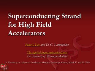
Superconducting Strand for High Field Accelerators. Peter J. Lee and D. C. Larbalestier The Applied Superconductivity Center The University of Wisconsin-Madison 1st Workshop on Advanced Accelerator Magnets, Archamps, France, March 17 and 18, 2003. Outline. High Superconductor Options

E N D
Superconducting Strand for High Field Accelerators Peter J. Lee and D. C. Larbalestier The Applied Superconductivity Center The University of Wisconsin-Madison 1st Workshop on Advanced Accelerator Magnets, Archamps, France, March 17 and 18, 2003
Outline • High Superconductor Options • Alternatives to Nb3Sn • 2212 • Nb3Al • MgB2 (Recent Enhancements to Hc2 at the UW) • Nb3Sn • Introduction to Fabrication Routes • Increased Critical Current Density • Where Does It Come From, What Are The Drawbacks • Design Implications • Summary of Recent Nb3Sn Results (UW) • Conductor Issues 1st Workshop on Advanced Accelerator Magnets, Archamps, France, March 17 and 18, 2003
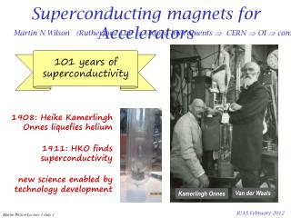
High Field Superconductors 2223 Tape B|| 2223 Tape B|_ Nb Al 3 ITER Nb Sn 3 ITER Critical Current Density, A/mm² Nb-Ti: Nb-47wt%Ti, 1.8 K, Lee, Naus and Larbalestier UW-ASC'96 10,000 Nb-44wt.%Ti-15wt.%Ta: at 1.8 K, monofil. high field optimized, At 4.2 K Unless unpubl. Lee, Naus and Larbalestier (UW-ASC) '96 Otherwise Stated Nb3Sn: Internal Sn-Rod OI-ST ASC2002 Nb Sn PIT 3 Nb3Sn: Internal Sn, ITER type low hysteresis loss design Nb Sn Internal Sn (IGC - Gregory et al.) [Non-Cu Jc] 3 Nb3Sn: Bronze route int. stab. -VAC-HP, non-(Cu+Ta) Jc, 2212 Round Wire Thoener et al., Erice '96. Nb3Sn: Bronze route VAC 62000 filament, non-Cu 0.1µohm-m 1.8 K Jc, VAC/NHMFL data courtesy M. Thoener. 1,000 Nb Al RQHT+2At%Cu 3 Nb3Sn: SMI-PIT, non-Cu Jc, 10 µV/m, 192 filament 1 mm dia. Nb Al 2 stage JR (45.3% Cu), U-Twente data provided March 2000 3 Nb Sn Tape Nb3Sn: Tape (Nb,Ta)6Sn5+Nb-4at.%Ta core, [Jccore, core ~25 % 3 of non-Cu] Tachikawa et al. '99 from (Nb,Ta) Sn 6 5 1.8 K Nb3Al: Nb stabilized 2-stage JR process (Hitachi,TML-NRIM, IMR-TU), Fukuda et al. ICMC/ICEC '96 Nb-Ti-Ta Nb3Al: 84 Fil. RHQT Nb/Al-Ge(1.5µm), Iijima et al. NRIM ASC'98 Paper MVC-04 Nb3Al: RQHT+2 At.% Cu, 0.4m/s (Iijima et al 2002) 100 Nb3Al: JAERI strand for ITER TF coil 1.8 K Nb Sn 3 Nb-Ti Bronze Bi-2212: non-Ag Jc, 427 fil. round wire, Ag/SC=3 (Hasegawa MT17 2000). MgB 2 Nb Sn Bi 2223: Rolled 85 Fil. Tape (AmSC) B||, UW'6/96 3 SiC 1.8 K Bronze PbSnMo S 6 8 Bi 2223: Rolled 85 Fil. Tape (AmSC) B|_, UW'6/96 PbSnMo6S8 (Chevrel Phase): Wire in 14 turn coil, 4.2 K, 1 10 µVolt/cm, Cheggour et al., JAP 1997 10 15 20 25 30 MgB2: 10%-wt SiC doped (Dou et al APL 2002, UW measurements) Applied Field, T
High Field Superconductors • Bi2212 • Highest Critical Currents above 14 T • Flat Jc vs B • Nb3Al • High Strength • High Critical Current Densities possible • MgB2 • Only 2 years old, HTS is now a venerable 17 years! • Very low cost raw materials, Ag not required. • With improved Hc2 provides both temperature and field margin. 1st Workshop on Advanced Accelerator Magnets, Archamps, France, March 17 and 18, 2003
Bi-2212 round wire has been cabled for accelerator magnets. • Jc(12 T, 4.2 K, non-silver) > 2000 A/mm2 in new material. • Long lengths( > 1500 m) are being produced. • Jc vs strain for Rutherford cables looks promising (LBNL results). • React/wind (BNL) and Wind/react (LBNL) coils are being made. Cable made at LBNL From Showa strand Ron Scanlan (LBNL) ASC2002 1st Workshop on Advanced Accelerator Magnets, Archamps, France, March 17 and 18, 2003
MgB2: first 2-gap superconductor Fermi surface from out-of-planep-bonding states of B pz orbitals: Dp(4.2K) 2.3 meV small gap Fermi surface from in-planes-bonding states of B pxy orbitals: Ds(4.2K) 7.1 meV large gap Choi et al., Nature 418 (2002) 758 V. Braccini et al. APS2003, Gurevich et al Nature University of Wisconsin-Madison
MgB2: There Are Mechanisms for increasing Hc2 2 gaps 3 impurity scattering channels • Intraband scattering within each s and p sheet • Interbandscattering • Increase Hc2 by: • Increasing r • Selective doping of s and p bands by substitutions for Mg by substitutions for B Hc2 is strongly enhanced as compared to the one-band WHH extrapolation Hc2(0) > 0.7 Tc H/c2(Tc)
Bulk: Resistivity enhancement after Mg exposure ….. 1.0 1.0 0.8 (40K) 0.6 (B) Slow cooled B C A (300K) 0.5 r/r (A) Original r 0.4 / r (C) Quenched 0 0.2 35 36 37 38 39 40 T [K] 0.0 0 100 200 300 Temperature [K] RRR: 15 3 r(40K): 1mWcm18mWcm [B] 14mWcm [C] 36.5 K [B] 37 K [C] Tc: 39 K V. Braccini et al. APL 2002 UW-ASC
… enhancement of Hc2 1.5 A 10 Hc2 mWcm r: 1 18 1.0 cm) 8 mW ( r 0.5 0T 9T 6 dHc2/dT: 0.51.2 (T/K) Upper critical field (T) 0.0 15 5 10 15 20 25 30 35 40 B 4 T (K) 12 cm) 9 2 mW ( 6 r 3 0 15 20 25 30 35 40 0 20 5 10 15 20 25 30 35 40 Temperature (K) C 37K39K T (K) 15 cm) 10 mW ( r 5 V. Braccini et al. APL 2002 UW-ASC 0 5 10 15 20 25 30 35 40 T (K)
Upper critical field depends very strongly on r B aged Untexured bulk samples suggest that MgB2 is capable of >30 T at 4.2 K and >10 T at 20 K. A B 33T resistive magnet at the NHMFL in Tallahassee, FL V. Braccini et al. APS2003
MgB2: Enhancement Summary-Films Gurevich et al (Nature) . . Etc. UW-Madison • Significant enhancement of Hc2 by selective alloying • Hc2 34 T, Hc2// 49 T (dirty film) • Hc2 29 T (untextured polycrystalline bulk) • Systematic changes in r, Tc, Hc2 in bulk and thin films • 2-band physics Thin films show that MgB2 is capable of higher Hc2 than even Nb3Sn. Wire expectation
So Why Nb3Sn? • Increasing Critical Current Density at Field Range for next generation of magnets. • Production Experience • Strand production • Cable production • Sub-scale dipole magnets • ITER CS Model Coil • Multiple Vendors • Cu Stabilizer • And $$$$$$$€€€€€€€¥¥¥¥¥¥¥ 1st Workshop on Advanced Accelerator Magnets, Archamps, France, March 17 and 18, 2003
Ron Scanlan (LBNL): ASC2002$/kA-m improvements mostly through Jc improvements: ITER D20 KSTAR RD-3 HD-1 Further cost improvements must come through process scale-up
Industrial Nb3Sn Fabrication Processes Bronze a Nb Filaments Diffusion Barrier Cu Cu Nb Sn Filaments Diffusion Barrier Cu • The bronze process continues to have a market for NMR where high n-value is important. High Cu:Sn ratios means Jc limited. • PIT produces deff=dfil and can produce high Jc but is expensive and is only commercially available from one manufacturer. • Internal Sn: Both Rod and MJR can produce 2900 A/mm² 12 T, 4.2 K. Large deff in high Jc strands. Bronze Process NbSn + Cu +Sn 2 Powder Nb Cu PIT – Powder in Tube Internal Sn (Rod Process Shown)
Overview of Nb3Sn Types ITER: Distributed Filaments. Large Cu sink for Sn. Variable and low Sn composition in A15 “High Jc” Low Cu, high Sn content in A15 and high homogeneity. Large or coalesced filaments.
Where is the Jc coming from? 12000 High Jc Internal Sn IGC EP2-1-3-2 700°C HT Layer Jc for low-loss ITER-style strand quite different to high Jc strand. High Jc Internal Sn: ORe110(695/96) SMI-PIT Nb-Ta Tube: 64 hrs@675 °C-small grains 10000 High Jc Internal Sn MJR TWC1912 504 Filament SMI-PIT, small grains only ITER: Mitsubishi Internal Sn ITER: LMI Internal Sn 8000 ITER: Furukawa Bronze Process ITER: VAC 7.5% Ta Bronze Process 23-24.5 At.% Sn in A15, equiaxed grains uniform across layer Layer Critical Current Density, A/mm² 6000 “high Jc” 4000 ITER low loss 2000 Nb3Sn 0 7 8 9 10 11 12 13 14 15 16 Applied Field, T 22-24 At.% Sn in A15, equiaxed to columnar transition “High Jc” strand has much less Cu (more hysteresis loss) and more Sn and Nb. High Sn levels maintained throughout reaction
Composition, Tc and Hc2 effects in Nb3Sn Devantay et al. J. Mat. Sci., 16, 2145 (1981) Charlesworth et al. J. Mat. Sci., 5, 580 (1970) Sn, Tc and Hc2 gradients! Nb3Sn is seldom Nb-25at%Sn Data compiled by Devred from original data assembled by Flukiger, Adv. Cryo. Eng., 32, 925 (1985)
“High Jc” in Internal Sn is achieved by reducing the Cu between the filaments to a minimum while maintaining Sn levels 2700 2600 2500 2400 Jc(A/mm²) 2300 2200 Calc. 2100 Meas. 2000 1900 30 35 40 45 50 55 At % Nb MJR can reach ~10:1 Nb:Cu in Filament pack. RIT ~ 4:1 A15 % in OI-ST MJR Sub-elements at 60% in the 2200 A/mm² strand Note the 10% variation through Sn redistribution during HT Outokumpu Advanced Superconductors (OAS) DOE-HEP CDP program reported by Ron Scanlan at ASC2002
“High Jc” A15 – Thick layers, shallow composition gradient, high Sn, low Cu (2200 A/mm², 12 T, 4.2 K) A15 Void Cu(Sn) Nb barrier Sn Diffusion Cu Nb3Sn Cu
Columnar are markers for local Sn deficiency 2 OI-ST MJR From Cu Islands OI-ST MJR From Voids IGC-RIT from Cu Islands 1.9 IGC-RIT from Voids 1.8 Aspect Ratio 1.7 2.4 2.2 2 1.6 Aspect Ratio 1.8 1.6 1.4 1.5 0 500 1000 1500 2000 Distance from Center of Original Nb (Rod) Filament, nm 1.4 0 200 400 600 800 1000 Distance from feature, nm Columnar A15 growth is observed when Sn supply is diminished Increased aspect ratio can be used to indicate reduced Sn in the A15 Using this method the local A15 inhomogeneity can be implied on a sub-micron scale. P. J. Lee, C. M. Fischer, M. T. Naus, A. A. Squitieri, D. C. Larbalestier, "The Microstructure and Microchemistry of High Critical Current Nb3Sn Strands Manufactured by the Bronze, Internal-Sn and PIT Techniques," Applied Superconductivity Conference , 2002. http://128.104.186.21/asc/pdf_papers/760.pdf
In low-Cu “high Jc” strand – Nb dissolution Nb dissolution causes loss in contiguous A15 area. Breach of the barriers by Sn enables LBNL SC group to control RRR by HT
OI-ST MJR Very High Jc:2900 A/mm², 12 T • MJR (ORe137): <15 volume % Cu in sub-element • Significant excess Sn even including barrier • The Sn core is larger than required to react all Nb and Nb(Ti) and form stoichiometric Nb3Sn Mike Naus (LTSW ’01) and PhD thesis 2002 shows important role of Sn:Nb in determining Tc and Hc2: http://128.104.186.21/asc/pdf_papers/theses/mtn02phd.pdf
Mike Naus: Universal Plot of Goodness 30 30 CRe1912, 4h650°C CRe1912, 4h650°C CRe1912, 4h650°C CRe1912, 180h650°C CRe1912, 180h650°C CRe1912, 180h650°C CRe1912, 4h750°C CRe1912, 4h750°C CRe1912, 4h750°C CRe1912, 256h750°C CRe1912, 256h750°C 24 24 CRe1912, 256h750°C ORe102, 4h650°C ORe102, 4h650°C 4.2 K ORe102, 4h650°C ORe102, 180h650°C ORe102, 180h650°C ORe102, 180h650°C ORe102, 4h750°C ORe102, 4h750°C ORe102, 4h750°C ORe102, 256h750°C ORe102, 256h750°C 18 18 ORe102, 256h750°C ORe110, 0.7 mm, 96h/695°C ORe110, 0.7 mm, 96h/695°C (T) (T) ORe110, 0.7 mm, 96h/695°C ORe110, 1.0 mm, 96h/695°C ORe110, 1.0 mm, 96h/695°C ORe110, 1.0 mm, 96h/695°C ORe137, 180h675°C ORe137, 180h675°C ORe139, 180h675°C ORe139, 180h675°C ORe137, 180h675°C Kramer 12 12 PIT, ternary, 4h/675°C PIT, ternary, 4h/675°C ORe139, 180h675°C H* H* PIT, ternary, 8h/675°C PIT, ternary, 8h/675°C PIT, ternary, 4h/675°C PIT, ternary, 64h/675°C PIT, ternary, 64h/675°C PIT, ternary, 8h/675°C 12 K PIT,ternary, 64h/800°C PIT,ternary, 64h/800°C PIT, ternary, 64h/675°C PIT, ternary, 8h/850°C PIT, ternary, 8h/850°C PIT,ternary, 64h/800°C 6 6 PIT, ternary, 8h/850°C 14 14 15 15 16 16 17 17 18 18 T T (K) (K) c,50% c,50% Mike Naus: LTSW 2001 Remarkably this plot includes non-alloyed, Ta and Ti alloyed Nb3Sn http://128.104.186.21/asc/pdf_papers/theses/mtn02phd.pdf
2900 A/mm² in OI-ST: also in RRP* • Nb-Ta alloy rod stack • More Cu remains between filaments than in MJR • Sub-elements very close together • Barrier breached and external A15 formed • RRR control feature?! • Some dissolution of Nb into core. • *1000m lengths available. • *(this note added in postcript thanks to Ron Scanlan – LBNL). *RRP=Rod Restack Process
2900 A/mm² in OI-ST RRP FESEM-BEI image showing barrier, sub-element spacing and Nb dissolution Cu(Sn) Core Nb barrier Stabilizer Cu Cu(Sn) Void A15
Sub-element uniformity: very good • Sub-element cross-sectional areas: • Coefficient of variation 2.7% - equivalent to good SSC Nb-Ti strand • Compares to 1.1-2.2 % for SMI-PIT B34 Filaments • 0.8 % for Edge Strengthened B134 Filament • But sub-elements are still too-large (~100µm) and the barriers too thin. 1st Workshop on Advanced Accelerator Magnets, Archamps, France, March 17 and 18, 2003
Microchemistry: Center of A15 layer • RRP 6445 2900 A/mm² HT and Jc by OI-ST (Kramer extrapolation) • Nb(Ta): 25.0 Atomic % Sn (Ignoring 1.4 At.% Cu signal) • 2900 A/mm² + Confirmed in transport by OI-ST in RRP6555-A, 0.8mm • SMI-PIT B134 80hrs at 675 °C, Jc (non-Cu) 1961 A/mm² 12 T • 24.0 Atomic % Sn (Ignoring 1.2 At. % Cu Signal) • SMI-PIT B34 64hrs at 675 °C, Jc (non-Cu) 2250 A/mm² 12 T • 24.1 Atomic % Sn (Ignoring 2.0 At. % Cu Signal) Conditions: FESEM EDS Analysis Same session, fresh calibration, 20 kV 1 sigma Sn error <0.22 Atomic % PIT Jc data: All measured by transport by UW
OI-ST 2900 A/mm² Strand: New Jcsc OI-ST 6445 RRP 0.9 mm (Parrell et al. ASC2002) 12000 OI-ST RRP 0.9 mm Kramer Extrapolation High Jc Internal Sn IGC EP2-1-3-2 700°C HT High Jc Internal Sn: ORe110(695/96) 10000 SMI-PIT Nb-Ta Tube: 64 hrs@675 °C-small grains High Jc Internal Sn MJR TWC1912 504 Filament SMI-PIT, small grains only ITER: Mitsubishi Internal Sn 8000 ITER: LMI Internal Sn ITER: Furukawa Bronze Process ITER: VAC 7.5% Ta Bronze Process Layer Critical Current Density, A/mm² 6000 4000 2000 0 7 8 9 10 11 12 13 14 15 16 Applied Field, T Non-Cu:A15 ratio from image analysis of high resolution FESEM images of 4 sub-elements OI-ST RRP 2900 A/mm² (12T, 4.2K) 1st Workshop on Advanced Accelerator Magnets, Archamps, France, March 17 and 18, 2003
Ta alloy rod produces larger grains ORe110 Ti alloy MJR OI-ST Ta alloy RRP
Ta alloy rod produces larger grains OI-ST Ta alloy RRP ORe110 Ti alloy MJR (d*~140 nm) (d*~180 nm)
A layer of large A15 grains surrounds the core – starting to look like PIT RRP: Outer row, outer layer Some morphology associated with original rods
Thus the Qgb must be higher . . . OI-ST 6445 RRP 0.9 mm (Parrell et al. ASC2002) OI-ST RRP 0.9 mm Kramer Extrapolation 16000 High Jc Internal Sn IGC EP2-1-3-2 700°C HT High Jc Internal Sn: ORe110(695/96) SMI-PIT Nb-Ta Tube: 64 hrs@675 °C-small grains 14000 ITER: High Jc Internal Sn TWC1912 Qgb 504 Filament SMI-PIT, excluding large grains ITER: Mitsubishi Internal Sn Qgb 12000 ITER: LMI Internal Sn Qgb ITER: Furukawa Bronze Process Qgb ITER: VAC 7.5% Ta Bronze Process Qgb 10000 Qgb in N/m² 8000 6000 4000 2000 0 7 8 9 10 11 12 13 14 15 16 Applied Field, T We calculate the specific boundary pinning force, QGB, using Kramer’s formalism: QGB=Fp/lSgb where l is an efficiency factor which accounts for the proportion of the grain boundary that is oriented for pinning. We apply a value of 0.5 for l, a value previously used for columnar grains OI-ST RRP 2900 A/mm² (12T, 4.2K) Grain Boundary Density from IA of ONE fracture image!
Fp Very High for “High Jc” Nb3Sn Nb-Ti: APC strand Nb-47wt.%Ti with 24vol.%Nb pins (24nm nominal diam.) - 100 Heussner et al. (UW-ASC) Nb Sn Nb Sn Internal Sn Nb-Ti: Best Heat Treated UW Mono- 3 3 Cu plated APC Nb Sn Filament. (Li and Larbalestier, '87) "High J " 3 c ITER Nb-Ti: Nb-Ti/Nb (21/6) 390 nm multilayer 2212 Tape '95 (5°), 50 µV/cm, McCambridge et al. (Yale) Nb3Sn: Sn plated Cu APC, 40 hr@650 °C, R. Zhou PhD Thesis (OST), '94 Nb-Ti MultiLayer (GN/m³) Nb3Sn: Mitsubishi ITER BM3 Internal NbN Sn p F Nb3Sn Strand: High Jc Internal Sn RRP Nb Al RIT 2223 (Parrell et al ASC'02) 3 10 Tape B|| Nb3Al: Transformed rod-in-tube Nb3Al Bulk Pinning Force, (Hitachi,TML-NRIM), Nb Stabilized - non- HT Nb-Ti Nb Jc, APL, vol. 71(1), pp.122-124), 1997 NbN: 13 nmNbN/2 nmAlN multi-layer || B, Gray et al. (ANL) Physica C, 152 '88 YBCO: /Ni/YSZ ~1 µm thick microbridge, H||ab 75 K, Foltyn et al. APC Nb-Ti (LANL) '96 Bi-2212: 19 filament tape B||tape face - Okada et al (Hitachi) '95 MgB 2 SiC Bi 2223: Rolled 85 Fil. Tape (AmSC) B||, UW'6/96 1 MgB2: 10%-wt SiC doped (Dou et al 0 5 10 15 20 25 APL 2002, UW measurements) Applied Field (T)
High Jc Internal Sn (twisted): 0.5% Bend Strain Nb3Sn is susceptible to filament breakage under small bend strains ~0.5% If the Nb3Sn layer us continuous (as in the prototype IGC-AS strand) breakage spans the entire tensile side. Compressive Nb3Sn Tensile Cu Barrier
PIT geometry leaves thick unreacted Nb and corners of hexagonal filaments. Nb or Nb-Ta tube Sn-rich powders Cu Commercial PIT strand is manufactured by Shapemetal Innovation BV, the Netherlands. This process was originally developed by ECN and is termed the ECN process. SMI-PIT filaments are otherwise remarkably homogeneous in area cross-section Before HT: Homogeneous stack of powder in Nb tubes After HT: Weakly bonded porous core left inside A15
Very high Sn levels can be achieved at elevated temperatures: PIT(Ta): SMI 34 64hrs@800C 25.20 (±0.1) At.%Sn* Nb(Ta) A15 Core 24.8 (±0.2) At.%Sn* 24.5 (±0.3) At.%Sn* * = ignoring Cu Very large grain sizes, however, result in low Jc
Powder-in-tube Nb(Ta): Twisted, 0.5% bend 300 Godeke et al. (Twente) IEEE Trans. Appl. SC, 9(2), 1999. I [A ] c 250 10 T , 4. 2 K 10 T , 6. 5 K 200 13 T , 4. 2 K 13 T , 6. 5 K 150 100 50 e [% ] a 0 - 0 . 4 - 0 . 2 0. 0 0 . 2 0. 4 0 . 6 0. 8 • No cracking seen at 0.5% strain (eventually cracks at 0.6%) • Although the Nb layer reduces the efficiency of the non-Cu package it applies more precompression to the A15 Matthew C. Jewell, Peter J. Lee and David C. Larbalestier, "The Influence of Nb3Sn Strand Geometry on Filament Breakage under Bend Strain as Revealed by Metallography", Submitted at the 2nd Workshop on Mechano-Electromagnetic Property of Composite Super-conductors, for publication in Superconductor Science and Technology (SuST), March 3rd 2003. http://www.cae.wisc.edu/%7Eplee/pubs/pjl-mcj-mem03-sust.pdf
Summary: Recent UW Nb3Sn Results • Remarkable improvements in the critical current densities (layer and non-Cu) of Nb3Sn have been observed in Nb3Sn strand fabricated by the PIT and Internal Sn process. • Grain Size of this Ta-alloyed conductor is small enough to yield high Jc but is larger (d*~180 nm) than found in Nb(Ti) MJR (d*~140 nm). • Remarkably high Qgb suggests that the grain boundary chemistry is different. • If Nb(Ta)3Sn grain size can be reduced without sacrificing stoichiometry further advances should be possible. • Effective filament diameter is 30 (PIT) -100 µm (Internal Sn) and needs to be improved. • PIT bend results suggest better strain tolerance could be achieved Lee: 1st Workshop on Advanced Accelerator Magnets, Archamps, France, March 17 and 18, 2003
Accelerator Conductor Issues • Can the effective filament size for “High Jc” Nb3Sn strand be reduced. • Can the cost of PIT strand be reduced? • Can the cost of all the other Nb3Sn strands be reduced? • Are we close to the limit for Nb3Sn strand Jc? • Can we engineer enough “Stress Relief” for Nb3Sn • Can Nb3Al be made in long lengths at low cost? • Will MgB2 continue to make gains, should it be supported? • Can the high Tc be exploited? Lee: 1st Workshop on Advanced Accelerator Magnets, Archamps, France, March 17 and 18, 2003
Bibliography • M. T. Naus, "Optimization of Internal-Sn Nb3Sn Composites," Ph.D. Thesis, Materials Science Program, University of Wisconsin-Madison, 2002. http://128.104.186.21/asc/pdf_papers/theses/mtn02phd.pdf • P. J. Lee, C. M. Fischer, M. T. Naus, A. A. Squitieri, D. C. Larbalestier, "The Microstructure and Microchemistry of High Critical Current Nb3Sn Strands Manufactured by the Bronze, Internal-Sn and PIT Techniques," Applied Superconductivity Conference , 2002. http://128.104.186.21/asc/pdf_papers/760.pdf • M. T. Naus, M. C. Jewell, P. J. Lee, D. C. Larbalestier, "Lack of Influence of the Cu-Sn Mixing Heat Treatments on the Super-Conducting Properties of Two High-Nb, Internal-Sn Nb3Sn Conductors," CEC-ICMC Advances in Cryogenic Engineering, 48[B], 1016-1022, 2002. http://128.104.186.21/asc/pdf_papers/698.pdf • C. M. Fischer, "Investigation of the Relationships Between Superconducting Properties and Nb3Sn Reaction Conditions in Powder-in-Tube Nb3Sn Conductors," M.S. Thesis, Materials Science Program, University of Wisconsin-Madison, 2002. http://128.104.186.21/asc/pdf_papers/theses/cmf02msc.pdf • C. M. Fischer, P. J. Lee, D. C. Larbalestier, "Irreversibility Field and Critical Current Density as a Function of Heat Treatment Time and Temperature for a Pure Niobium Powder-in-Tube Nb3Sn Conductor," CEC-ICMC Advances in Cryogenic Engineering, 48[B], 1008-1015, 2002. http://128.104.186.21/asc/pdf_papers/704.pdf • P. J. Lee, C. D. Hawes, M. T. Naus, A. A. Squitieri, D. C. Larbalestier, Compositional and Microstructural Profiles across Nb3Sn Filaments", IEEE Transactions on Applied Superconductivity, 11(1), pp. 3671-3674, 2001. http://128.104.186.21/asc/pdf_papers/662.pdf • Matthew C. Jewell, Peter J. Lee and David C. Larbalestier, "The Influence of Nb3Sn Strand Geometry on Filament Breakage under Bend Strain as Revealed by Metallography", Submitted at the 2nd Workshop on Mechano-Electromagnetic Property of Composite Super-conductors, for publication in Superconductor Science and Technology (SuST), March 3rd 2003. http://www.cae.wisc.edu/%7Eplee/pubs/pjl-mcj-mem03-sust.pdf • R. M. Scanlan, “Conductor development for high energy physics-plans and status of the US program,”, IEEE Transactions on Applied Superconductivity, 11(1) , pp: 2150 –2155, Mar 2001. http://ieeexplore.ieee.org/iel5/77/19887/00920283.pdf?isNumber=19887&prod=IEEE+JNL&arnumber=920283&arSt=2150&ared=2155&arAuthor=Scanlan%2C+R.M.%3B • R. M. Scanlan, D. R. Dietderich, Progress and Plans for the U. S. HEP Conductor Development Program, ASC2002 presentation 5LA04. • V. Braccini, L. D. Cooley, S. Patnaik, P. Manfrinetti, A. Palenzona, A. S. Siri, D. C. Larbalestier, "Significant Enhancement of Irreversibility Field in Clean-Limit Bulk MgB2," APL, 9 Dec. 2002; 81(24): 4577-9. http://arxiv.org/ftp/cond-mat/papers/0208/0208054.pdf
Acknowledgments • Ron Scanlan (LBNL): Who leads the US-DOE HEP Conductor Development Program supplied additional slides. • Jeff Parrell, Mike Field and Seung Hong at OI-ST have advanced the properties of Nb3Sn at a remarkable rate and have provided strand samples to both Labs and Universities. • Tae Pyon and Eric Gregory (now with Accelerator Technology Corp) of IGC-AS (now Outokumpu Advanced Superconductors) supplied additional internal Sn strands for these studies. • Jan Lindenhovius of Shapemetal Innovation BV, supplied the UW with PIT strand for these studies. • Mike Naus and Chad Fischer (now with Intel) provided much of the internal Sn and PIT (respectively) data presented here as graduate students at the University of Wisconsin-Madison