Download
1 / 15
150 likes | 250 Views
Diurnal Emission Control October 7th, 2008. Sources of Hydrocarbon Emissions. Permeation – through fuel tank walls Spillage/Spitback – during fuel fill Exhaust – during engine operation Diurnal emissions – due to daily temperature cycles. 2. California/EPA Diurnal Emission Limits.

E N D
Diurnal Emission Control October 7th, 2008
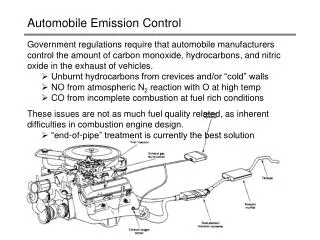
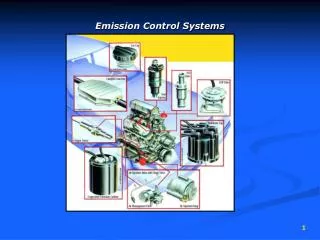
Sources of Hydrocarbon Emissions Permeation – through fuel tank walls Spillage/Spitback – during fuel fill Exhaust – during engine operation Diurnal emissions – due to daily temperature cycles 2
California/EPA Diurnal Emission Limits • Trailerable boats (<8.5ft beam & <26ft LOA): • Less than .4 grams per gallon per day of hydrocarbon emissions. • Non-trailerable boats (>8.5ft beam or >26ft LOA): • Less than .16 grams per gallon per day of hydrocarbon emissions. 3
How to Meet Diurnal Emissions Standards • Utilization of a carbon canister system • Currently the standard in the auto industry • Fairly easy installation with low risk • Pressurized fuel system (1 psi) • Higher risk if connections fail – potential of significant fuel leakage in hull of vessel • May require alternative fittings or connection methods • Currently not recommended by the USCG 4
Carbon Canister Basics • Required size of canister is determined by the length/width of the boat as well as the capacity of the fuel tank • Liquid water must not enter the canister • Adequate care must be taken so that liquid fuel does not enter the canister • The canister should be mounted above the top level of the fuel tank • “Marine Grade” carbon is required • ABYC requires that the vent line be “self-draining” 5
Carbon Canister Available Sizes • 1L • 1.5L • 2L • 3L • 4L • Two or more canisters can be “daisy chained” together for increased capacity or to facilitate installation 7
Installation Examples • Recent high-performance builder carbon canister installation examples: 8
Fit-up Key Findings Diurnal emission control does not allow for a “component solution”. A system perspective is required. 10
P-Trap 2L Carbon Canister In Line Surge Protector Sean Whelan Product Development Engineer Hardware, Fuel & Trailering Categories phone/fax (616) 897-2275 / (616) 897-2218 Brunswick Confidential
Key Installation Notes Builders will need to ensure no water of fuel comes in contact with the carbon canister A P-Trap vent or similar device should prevent water intrusion Surge protectors are needed to prevent fuel from entering the canister 13
Summary • Each boat application presented different challenges, builders should not wait until the last minute to spec in the system • There are alternative ways to meet various EPA guidelines, talk with your fuel system provider ahead of time to understand your options and minimize costs • The proposals are now implemented, builders can’t take a wait and see attitude • We recommend partnering with a systems provider vs. component supplier to ensure your boats meet the latest fuel system regulations 14