Download
1 / 31
310 likes | 465 Views
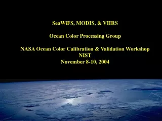
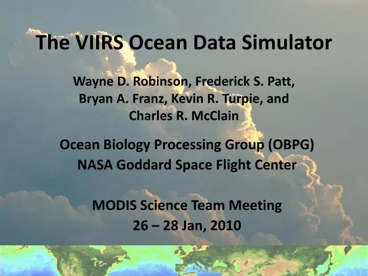
Wayne D. Robinson, Frederick S. Patt, Bryan A. Franz, Kevin R. Turpie, and Charles R. McClain. The VIIRS Ocean Data Simulator. Ocean Biology Processing Group (OBPG) NASA Goddard Space Flight Center MODIS Science Team Meeting 26 – 28 Jan, 2010. Goals of the VIIRS Ocean data Simulator.

E N D
Wayne D. Robinson, Frederick S. Patt, Bryan A. Franz, Kevin R. Turpie, and Charles R. McClain The VIIRS Ocean Data Simulator Ocean Biology Processing Group (OBPG) NASA Goddard Space Flight Center MODIS Science Team Meeting 26 – 28 Jan, 2010
Goals of the VIIRS Ocean data Simulator • Provide realistic, higher fidelity view of what VIIRS data will look like prior to launch • Create data to help assess the impact of instrument artifacts (eg. Cross-talk…) • To generate sufficient quantities of simulated VIIRS data to test the capabilities of product generation within the mini-IDPS and evaluation within the PEATE. • A diagnostic tool for EDR analysis
Simulator Design • Use existing OBPG system and software as much as possible • requires only enhancement (for the VIIRS instrument type) and expanded capabilities (for better simulation) • System can direct computer resources to simulate many data granules • Use common processing algorithms that are used for processing other instrument data • The main new software is viirs_sim_sdr – create the VIIRS SDR files
Simulator Design, continued • Create Top of Atmosphere (TOA) radiances as seen by the VIIRS instrument for realistic ocean scenes, with realistic atmospheric effects – aerosols… and clouds, land • Create realistic VIIRS Sensor Data Record (SDR) to contain calibrated TOA radiances, location and metadata • The ocean scene, atmospheric information and land, cloud are derived from other ocean color instrument data(SeaWiFS, MODIS Aqua, Terra)
Elements in the VIIRS Simulator • Simulator initial steps • Simulate VIIRS viewing geometry • Create empty VIIRS SDR • Create the surface data scene from existing satellite data • Ocean color scene (ocean information) • Surface reflectance scene (cloud, land information) • Select scene data at the SDR locations • Ocean color • Reflectance • Create TOA radiances as VIIRS sees them and place them in the SDR file • Propagate ocean data to TOA • Place ocean data into SDR • Convert cloud / land reflectance to TOA and add into the SDR • Add instrument artifacts
Detail of simulation steps • NPP orbit used for the day of 1 Jan, 2006 • A region of the Mediterranean is selected to show the cloud and land inclusion • MODIS-A / SeaWiFS data from 1 – 2 Jan 2006 were averaged to make an ocean / reflectance scenes with inter-orbit gaps filled • 4 VIIRS SDR granules were simulated for this region with start times: 11:57:14, 11:58:40, 12:00:05, and 12:01:31 UTC, each standard size 768 lines
VIIRS Ocean Color Simulation – Geolocation generarion 1a. Simulator initial steps VIIRS orbit elements (TLE) Generate granule geolocation (gen_scan_geo) VIIRS orbit data SGP orbit computation Geolocation at VIIRS (aggregated) pixels 1a
VIIRS Ocean Color Simulation – Empty SDR creation 1. Simulator initial steps VIIRS orbit elements (TLE) Generate granule geolocation (gen_scan_geo) VIIRS orbit data SGP orbit computation Geolocation at VIIRS (aggregated) pixels Simulate VIIRS SDR (viirs_sim_sdr) VIIRS SDR 1b
VIIRS Ocean Color Simulation – Ocean scene creation 1. Simulator initial steps VIIRS orbit elements (TLE) Generate granule geolocation (gen_scan_geo) VIIRS orbit data SGP orbit computation 2a. Surface data scene creation – Ocean Color Geolocation at VIIRS (aggregated) pixels MODIS Aqua granules Simulate VIIRS SDR (viirs_sim_sdr) Level-3 binning Level-3 scene of ocean color data VIIRS SDR 2a
VIIRS Ocean Color Simulation – Land, cloud scene creation 2b. Surface data scene creation – SFC Refl 1. Simulator initial steps VIIRS orbit elements (TLE) Generate granule geolocation (gen_scan_geo) SeaWiFS granules L3 binning of reflectance VIIRS orbit data SGP orbit computation Reflectance L3 2a. Surface data scene creation – Ocean Color Geolocation at VIIRS (aggregated) pixels MODIS Aqua granules Simulate VIIRS SDR (viirs_sim_sdr) Level-3 binning Level-3 scene of ocean color data VIIRS SDR 2b
VIIRS Ocean Color Simulation – Ocean data selection 2b. Surface data scene creation – SFC Refl 1. Simulator initial steps VIIRS orbit elements (TLE) Generate granule geolocation (gen_scan_geo) SeaWiFS granules L3 binning of reflectance VIIRS orbit data SGP orbit computation Reflectance L3 2a. Surface data scene creation – Ocean Color Geolocation at VIIRS (aggregated) pixels MODIS Aqua granules Simulate VIIRS SDR (viirs_sim_sdr) Level-3 binning Level-3 scene of ocean color data VIIRS SDR Get ocean color at VIIRS locations (vcaltarget) Ocean color at VIIRS locations 3a 3a. Select data at SDR locations – Ocean Color
Ocean Color Simulation – Land, cloud data selection 2b. Surface data scene creation – SFC Refl 1. Simulator initial steps VIIRS orbit elements (TLE) Generate granule geolocation (gen_scan_geo) SeaWiFS granules L3 binning of reflectance VIIRS orbit data SGP orbit computation Reflectance L3 2a. Surface data scene creation – Ocean Color Geolocation at VIIRS (aggregated) pixels 3b. Select data at SDR locations – SFC Refl Get reflectance at VIIRS locations (l1_extract_l3 MODIS Aqua granules Simulate VIIRS SDR (viirs_sim_sdr) Reflectance at VIIRS locs Level-3 binning Level-3 scene of ocean color data VIIRS SDR Get ocean color at VIIRS locations (vcaltarget) Ocean color at VIIRS locations 3b 3a. Select data at SDR locations – Ocean Color
VIIRS Ocean Color Simulation – TOA radiances in SDR 2b. Surface data scene creation – SFC Refl 1. Simulator initial steps VIIRS orbit elements (TLE) Generate granule geolocation (gen_scan_geo) SeaWiFS granules L3 binning of reflectance VIIRS orbit data SGP orbit computation Reflectance L3 2a. Surface data scene creation – Ocean Color Geolocation at VIIRS (aggregated) pixels 3b. Select data at SDR locations – SFC Refl Get reflectance at VIIRS locations (l1_extract_l3 MODIS Aqua granules Simulate VIIRS SDR (viirs_sim_sdr) Reflectance at VIIRS locs Level-3 binning Level-2 dataset with VIIRS TOA radiances) Level-3 scene of ocean color data VIIRS SDR Get ocean color at VIIRS locations (vcaltarget) 4. Make TOA rads, for SDR Level-2 to level-1 (l2gen inverse) Ocean color at VIIRS locations 4 3a. Select data at SDR locations – Ocean Color
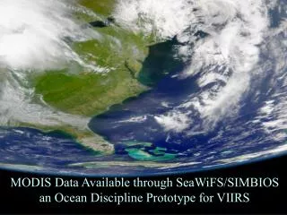
True color of simulated VIIRS granules (satellite projection)
Additional work to be done • Test simulated VIIRS granule processing in the Mini IDPS • Insert tables derived from the VIIRS characterization (in l2gen) • Add option to modify TOA radiances with instrument artifacts (in viirs_sim_sdr) • Generate multi-day full-earth simulated VIIRS granule set for analysis work
Summary • The VIIRS simulator produces simulated VIIRS SDR granules with • High fidelity ocean color • Reasonable cloud and land radiances • Simulator requires 2 major improvements to perform the desired goals • Other granule tests will be performed • Generate global data sample
1a. Simulate orbit, geolocation • Derive locations and view angles for every sample viewed by VIIRS • Start with orbit description for NPP (two line elements or TLE) • SGP 4 model (Proj Spacetrack) generates NPP orbit position for every minute • Use nominal attitude, earth model, and VIIRS scan geometry to derive sample ground locations and viewing angles • Use solar model to derive sun zenith, azimuth
1b. Simulate empty SDR • Create standard VIIRS SDR conforming to NPOESS Common Data Format Control Book • Use locations and viewing geometry to fill the SDR geolocation dataset • Insert placeholder nominal TOA radiances into the M-band SDR files • Add proper identifying metadata • New program: viirs_sim_sdr is used for this purpose
2. Create separate ocean data and reflectance scenes • Use existing ocean color bands from instruments with similar bands to VIIRS (MODIS Aqua and others) • Accumulate data over sufficient # orbits to attain complete areal coverage (usually, 2 days at least). • Ocean data includes normalized water-leaving radiances, Angstrom coefficient, and AOT • Land / cloud data is reflectance in all bands • Use existing ODPS program l2bin
3. Select data at VIIRS locations • Extract surface data from scenes for locations in VIIRS granules: • Ocean: normalized water-leaving radiances, Angstrom and AOT aerosol information • Land / clouds: reflectance in VIIRS bands • Use locations defined by the initial VIIRS SDR geolocation • Create a binary files containing the ocean color, overlying aerosol, and reflectance at VIIRS locations
4. Simulate SDR – Ocean color to TOA • Use standard OBPG program: l2gen. Normal use is to derive ocean color from TOA radiances • For our use, operate l2gen in reverse to add atmospheric effects, as seen by VIIRS, to the surface radiances to get TOA radiances • Save atmospheric information for use with reflectance data
4. Simulate the complete SDR • Use the viirs_sim_sdr program again but inserting the TOA ocean radiances into the M-band radiances • Bring reflectance to TOA (adding atmospheric effects) and fill / replace TOA radiances with cloud and land TOA radiances • Optionally add instrument artifacts to radiances • Optionally perform bow tie deletion