Download
1 / 40
400 likes | 554 Views
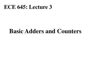
Building Adders & Subtractors. Goals. By the end of this lecture, you should understand… How to build a Half-Adder How to build a Full-Adder How to use Adders to perform subtraction. What We Can Do. Last time, we learned how to build a circuit that met functional requirements.

E N D
Goals By the end of this lecture, you should understand… • How to build a Half-Adder • How to build a Full-Adder • How to use Adders to perform subtraction
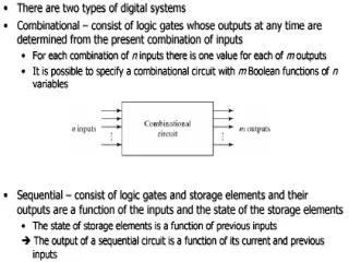
What We Can Do • Last time, we learned how to build a circuit that met functional requirements. • Today, let’s build a circuit that performs a specific engineering function and supports two output lines – we’ll build a circuit to add two binary numbers …
Problem Definition • We will start out simply, adding two single digit binary numbers • Let’s make certain we can do this by hand before we construct the circuit • There are four possible combinations of single digit, two number addition: • 0 + 0 =0 • 0 + 1 = 1 • 1 + 0 = 1 • 1 + 1 = 10
Problem Analysis • Notice that one of the combinations of two single digit additions is a double digit number, created by a carry:1 + 1 = 10
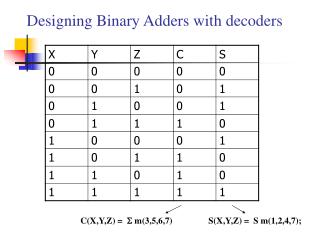
Standardized Output • We’ll use leading zeros in order to produce a standard output:0 + 0 = 00 (0 plus 0 equals 0)0 + 1 = 01 (0 plus 1 equals 1)1 + 0 = 01 (1 plus 0 equals 1)1 + 1 = 10 (1 + 1 equals 10) • Notice that all of our answers include two bits. By putting the output in standardized form, we can stipulate the behavior of both outputs given any combination of two inputs with the following truth table …
Breaking Down the Truth Table • Notice the Q column (carry line) from the truth table? Recognize it? It’s an AND!:Q = A • B
Breaking Down the Truth Table • What about the R column (sum line)? What sub-expression could we use? What do you notice about the R column? • R is high iff one and exactly one input is high …
Breaking down the Truth Table • “R will be high iff one and exactly one input is high.” • What expression can we use to prove this statement?R = (~A • B) + (A • ~B)
A B Circuit Diagram • Q = (~A • B) + (A • ~B) Q
A Short Cut • The circuit we created to diagram our R column is so common in circuit design that it has a special name. It is called an Exclusive Or. It is usually labeled XOR or drawn as a plus sign with a circle around it. • From our truth table, we can derive the following statement: “Our adding circuit should consist of an XOR gate (for R output, the Sum line) and an AND gate (for Q output, the Carry line).
More on XOR • We have already established that any circuit can be created as a combination of 3 basic gates: NOT, AND and OR. • Although not one of the fundamental gates, the XOR gate is common enough that it is called a derived gate. • We can build the XOR from the primitive gates. However, engineers use the XOR so often they’ve given XOR its own symbol …
A Q B Q = A B + XOR Symbol • The symbol for the XOR Gate:
Re-Writing the Truth Table • The XOR circuit delivers the Sum Line (R) of adding two single digits. • The AND circuit produces the Carry Line (Q). • We’ve just created a fundamental circuit called a Half Adder, which provides the capability of adding two single bit numbers. +
A RSUM QCARRY B Circuit Diagram for the Half Adder
Using the Half-Adder as a Building Block • The Half-Adder circuit is more powerful than you might think. It operates as the key component in a divide-and-conquer approach to adding n digits. • How does this work? The first leap of faith comes in realizing that three single digit numbers could be added two at a time: • First, add the first two digits together using a half-adder. • Then, add the result of this sum to the third number using another half-adder.
Full Adder • Let’s try to add 3 single digit numbers by stringing together two half-adders: • We need 3 input lines, one for each number. • Two input lines feed into the first half adder; the third input line functions as a carry-in line. • The second half-adder has two input lines: the output sum from the first half-adder, plus the third, carry-in input line. • The next slides show the truth table for the Full Adder and then the circuit diagram for the Full Adder …
A RSUM B QCARRY CIN Circuit Diagram for the Full Adder
A FULLADDER QCARRY B RSUM CIN Shorthand Notation for the Full Adder • The full adder is usually drawn in a shorthand notation:
Interpreting the Full Adder Circuit • Do you see any patterns between the output lines and the input lines? • If you look at the truth table, you can see that the QCARRY output line is true if and only if exactly two or three input lines are high. • Also, the RSUMoutput line is high when the XOR of A and (the sum of Input B and CIN) is high? In other words, add the Input B and CIN values together, as though you were putting them through a half adder. Take the result, and XOR it with the value of the A input line. The result is the value for the RSUM output line
Summarizing the Full Adder • By connecting two half-adders together, we can add 3 single digit binary numbers • It shouldn’t come as a surprise to learn that by stringing even more half-adders together, we can add even more single digit numbers…
The N-Bit Adder • The next leap of faith is to move from adding 3 (or more) single digit numbers to adding multi-bit numbers • First, note that the sum of adding two N-bit numbers can be N + 1 bits • This comes as a result of possibly obtaining a carry into the next column • Adding N-bit numbers isn’t an abstract consideration – it’s a real computing operation - at a minimum, a modern computer would add 16 bit numbers, done with a 16-bit adder
The N-Bit Adder • Here is the general rule: to add two N-bit numbers, N full adders are required, one for each column in the sum • The first 2 inputs for each full adder come from the digits in the numbers to be added • The carry-out produced for each column is used as the carry-in for the next column to the left • At some point, you can have overflow as you exceed the adder circuitry capability.
Getting Real • The processing component of the ALU – the arithmetic logic unit – uses Adder circuitry to perform fundamental arithmetic operations. • By connecting half adders to make a full adder, and multiple full adders in a chain, we now can work our way to simple addition. • Other operations are a variation on this fundamental capability …
How to Subtract • What other arithmetic operations do we need to be able to perform with circuits? • The next logical step would be to tackle subtraction … • We could come up with a separate subtraction circuit, and some clever scheme of knowing which circuit to activate based on what kind of math problem we encountered • It turns out that the solution is more elegant -- it uses the approach we have seen repeatedly: turn a new problem into a problem we have already solved …
From Subtraction to Addition • What we have is a circuit that can add numbers. We want to make this circuit also work for subtracting two numbers… • Let’s rethink our problem, with a specific example: 5 - 2 = 3, or, put another way:5 + (-2) = 3 • Now, we have an addition problem, instead of subtraction. This means our existing circuit will work we could unlock how to represent negative numbers, like -2.
Two’s Complement • Remember that we can represent negative numbers using a scheme called Two’s Complement. • In two’s complement, to encode a negative number, you take its positive value, complement it, and then add one. • The resulting number will be in two’s complement form.
Review of Two’s Complement • Convert each number from Base-10 to its Base-10 format (we’ll use four-bit numbers); for negative values, convert their absolute value:510 = 01012|-210|= 00102
Review of Two’s Complement • Complement the negative value, changing all 1s to 0s and all 0s to 1s. The result is called a One’s Complement:00102 11012
Review of Two’s Complement • Add 1 to the One’s Complement. The result is your original negative number in Two’s Complement form:-210 00102 11012 + 12 = 11102
Problem Solution • Then, we add the first number of our problem (510 or 01012) to this two’s complemented number: 01012 + 11102 = 100112 • If we throw away the carry line (the leftmost 1), our answer is correct: 00112 = 310 • Is that legal? Why or why not? We are restricting ourselves here to 2, 4-bit numbers. We can choose to simply ignore the carry line (the 5th bit).
Building It with Circuits • Can we make this fly with our circuitry? • Let’s map each step… • The first step was to create the two’s complement of the number we subtracted. • We did this in a two-step process: first we took the one’s complement, then added one to get the final two’s complement.
The Circuitry of Two’s Complement • How would we take one’s complement? • A NOT gate would work here…. Any number you put in, the NOT gate would reverse • The next step would be to add one… we could use an addition circuit, to make certain one was added. • Now we have the two’s complemented number, and it is combined with the first number in an adder circuit to produce an answer.
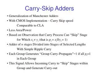
Pretty Close • This is pretty close to how subtraction is actually performed in a computer. • There are a few tweaks for efficiency and minimal circuit design • The second step of two’s complement requires you to add one, and we could do this with an adder. However, do you remember how we built our multi-bit adder by stringing together multiple adders?
4-bit Full Adder • Note that the bottom full adder in this 4 bit adder has an unused carry in line (at the bottom of the picture). If we make this line high, it would have the same effect as adding one… and that is how the add one part of two’s complement is achieved. This cuts down on the needed circuitry for subtraction.
Summary of Subtractors • Represent the subtraction problem as an addition problem by adding a negative value of the number. • We can represent negative numbers using Two’s Complement. • Once we have converted the subtraction problem to an addition problem, we can use an adder, built from a half-adder consisting of an And and an XOR gate.
Subtraction: The Rule • By using the two’s complement approach, the following rule applies for performing the arithmetic operation of subtraction:“X – Y can be computed by adding the negative of Y to X using addition circuitry designed for positive numbers, and ignoring any carry-out that is produced.”