Download

1 / 22
250 likes | 489 Views
Fuel Injection Placement. Bryce Tillman David Mengelkoch. Fuel Injection VS. Carburetion. Changed an originally carbureted intake to use fuel injection (FI) Advantages: Easier to tune Fewer parts Easier maintenance Adapts to environmental conditions. Our Project.

E N D
Fuel Injection Placement Bryce Tillman David Mengelkoch
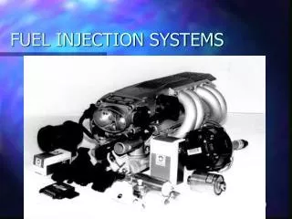
Fuel Injection VS. Carburetion • Changed an originally carbureted intake to use fuel injection (FI) • Advantages: • Easier to tune • Fewer parts • Easier maintenance • Adapts to environmental conditions
Our Project • KTM 525 4-stroke engine • Fuel Injected • E-85 • Turbocharged • Intercooled • Intake system restriction
Co-Flow and Opposing Flow • Co-Flow: fuel is injected in the same direction as the air stream entering the engine • Opposing Flow: fuel is injected in the opposite direction as the air stream entering the engine
FI Placement Co-flow Opposing flow
Measurement Comparisons • Effects of Co-flow Vs. Opposing flow FI • Intake air cooling • Engine horsepower • Brake Specific Fuel Consumption (BSFC) (lb/hp-hr) • Fuel vaporization
Hypothesis Co-Flow • Higher horsepower • Lower BSFC • Less cooling effect • Better engine stability Opposing Flow • Lower horsepower • Higher BSFC • More cooling effect • Difficulty idling
Co-Flow Simulation Fuel in Air in Co-Flow Velocity ~ 50 m/s at Intake Port
Opposing Flow Simulation Fuel in Air in Opposing Flow Velocity ~ 15 m/s at Intake Port
Co-Flow Simulation Fuel in Air in Co-Flow Fuel Mixture
Opposing Flow Simulation Fuel in Air in Opposing Flow Fuel Mixture
Construction of Co-flow FI Placement
Construction of Opposing Flow FI Placement
Temperature Readings Pre-FI post turbo measurement
Temperature Readings Post FI measurement
Co-flow Results Max HP: 64 @ 7000 RPM Max Torque: 57.3 ft-lbs @ 5400 RPM
Opposing Flow Results Max HP: 73 @ 6300 RPM Max Torque: 64.9 ft-lbs @ 5300 RPM
Temperatures • Co-flow • Max post turbo temp: 257°F • Max post FI temp: 80°F • Average temperature drop: 158.36 °F • Opposing flow • Max post turbo temp: 268°F • Max post FI temp: 87°F • Average temperature drop: 152.96 °F
BSFC • Co-flow • Average BSFC: 0.914 lb/hp-hr • Opposing flow • Average BSFC: 0.647 lb/hp-hr
Conclusion Co-Flow • Lower horsepower • Higher BSFC • Less cooling effect • Better engine stability Opposing Flow • Higher horsepower • Lower BSFC • More cooling effect • Difficulty idling
References Pulkrabek, Willard W. Engineering Fundamentals of the Internal Combustion Engine. Upper Saddle River, NJ: Prentice Hall, 1997. Print. Sches, Celine, StephaneGuilain, and FadilaMaroteaux. Modeling of the Fuel Behavior in the Intake Manifold of a Port-Injected Spark-Ignition Engine. Diss. Paris University, 1997. Warrendale: Society of Automotive Engineers, 1997. Print. Wegleitner, Joseph A., Scott A. Miers, Ryan D. Hayes, Scott P. Heim, Dan P. Hoffman, and Bernhard P. Bettig. Design and Testing of a Single Cylinder, Turbocharged, Four-Stroke Snowmobile with E.F.I. and Catalytic Exhaust Treatment. Diss. Michigan Technological University, 2002. Warrendale: Society of Automotive Engineers, 2002. Print.