Download
1 / 29
290 likes | 430 Views
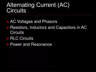
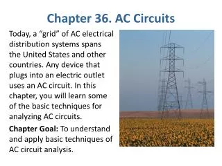
AC Circuits & Phasors. We want to understand RLC circuits driven with a sinusoidal emf. First: engineers characterize the amplitude of a sinusoidal emf with the “root mean square” (rms) value.

E N D
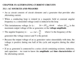
We want to understand RLC circuits driven with a sinusoidal emf. First: engineers characterize the amplitude of a sinusoidal emf with the “root mean square” (rms) value. (This is because the power dissipated in a resistor is I2R or V2/R… if we want to use an I or a V from a sine wave emf, we have to use the rms I or V. )
Which phasor shows a current that is positive and increasing? Which phasor shows a current that is negative with an increasing magnitude (i.e. getting more negative?)
X = “reactance”; the effective combination of Xs in a circuit is called “impedance.”
At high frequencies, the reactance of what circuit element decreases?A] resistorB] capacitorC] inductorD] none decreaseE] all decrease Low reactance is like low resistance… small voltage drop for a large current.
An AC voltage source drives a sinusoidal current through two resistors. The amplitude of the sinusoidal voltage across the top resistor is 4 V. The amplitude of the sinusoidal voltage across the bottom resistor is 3 V. What is the amplitude of the sinusoidal voltage provided by the source? A] 0 V D] 7 V B] 1 V E] 12 V C] 5 V
An AC voltage source drives a sinusoidal current through a resistor and an inductor in series. The amplitude of the sinusoidal voltage across the top resistor is 4 V. The amplitude of the sinusoidal voltage across the bottom inductor is 3 V. What is the amplitude of the sinusoidal voltage provided by the source? A] 0 V D] 7 V B] 1 V E] 12 V C] 5 V
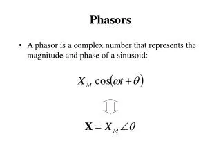
Phasors The x axis projection is the instantaneous value. The length is the amplitude. V=iX says the LENGTH of the voltage phasor is proportional to the LENGTH of the current phasor. The proportionality constant is the reactance, X.
Circuit elements in series have the same current phasor. The voltage phasors add (like vectors) to give the total voltage. Circuit elements in parallel have the same voltage phasor. The current phasors add (like vectors) to give the total current.
An AC voltage source drives a sinusoidal current through a capacitor and a resistor in series. The amplitude of the sinusoidal voltage across the top capacitor is 4 V. The amplitude of the sinusoidal voltage across the bottom resistor is 3 V. What is the amplitude of the sinusoidal voltage provided by the source? A] 0 V D] 7 V B] 1 V E] 12 V C] 5 V
An AC voltage source drives a sinusoidal current through a capacitor and an inductor in series. The amplitude of the sinusoidal voltage across the top capacitor is 4 V. The amplitude of the sinusoidal voltage across the bottom inductor is 3 V. What is the amplitude of the sinusoidal voltage provided by the source? A] 0 V D] 7 V B] 1 V E] 12 V C] 5 V
If we change frequency, we change the reactance X of the cap and the inductor. If we increase the frequency: Both X’s go up XL goes up, but Xc goes down Xc goes up, but XL goes down Both X’s go down. Recall V=iX
If we change frequency, we change the reactance X of the cap and the inductor. If we increase the frequency: Both X’s go up XL goes up, but Xc goes down Xc goes up, but XL goes down Both X’s go down. Recall V=iX… if we raise the frequency, we can make the amplitude of the voltage across the inductor = amplitude of the voltage across the cap.
At the special frequency where the the reactance of the inductor = reactance of the capacitor: A] the current will be zero B] the current will be infinite, for any finite applied voltage Recall V=iX… if we raise the frequency, we can make the amplitude of the voltage across the inductor = amplitude of the voltage across the cap.
This is called resonance. Real circuits must have a little resistance, so the current, though large, remains finite. But at the resonance frequency, a very small driving voltage gives a very large current. The directions of the voltage drop in the cap and in the inductor are opposite. The directions of the current in the cap and the inductor are the same. (in series.)
Phi is the phase angle between current and voltage.
Our wavefront satisfies both “Gauss’s laws” because there is no enclosed charge or current, and fields on opposite sides of the box are the same.
There is a changing B flux as the wavefront moves by. This changing flux must be equal to the line integral of the E field. Only the back edge (gh) contributes to this line integral.
There is a changing E flux also. This gives another reqd relation between E and B.
Accelerating Charges Radiatehttp://www.its.caltech.edu/~phys1/java/phys1/MovingCharge/MovingCharge.html#
Coulomb’s law can’t describe the “kinked” E field. We got it from connecting field lines (Gauss’ law!) + geometry. So, while Gauss “derived” his law from Coulomb, Gauss’ Law is better.It’s always true, while Coulomb’s law is only true for unaccelerated charges.