Download
1 / 26
280 likes | 293 Views
ECE2799 - Engineering Design Thermal Considerations. Prof. Mazumder Prof. Bitar. Updated 11/16/2017. Heat Flow. Heat (Power) flows from an area of higher temperature To lower temperature 3 Heat flow mechanisms Conduction transferring heat through a solid body

E N D
ECE2799 - Engineering DesignThermal Considerations Prof. Mazumder Prof. Bitar Updated 11/16/2017
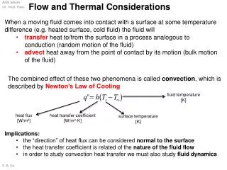
Heat Flow • Heat (Power) flows from an area of higher temperature To lower temperature • 3 Heat flow mechanisms • Conduction transferring heat through a solid body • Power easily flows thru high thermal conductivity material (e.g. copper, aluminum) • Convection heat is carried away by a moving fluid • Free convection • Forced convection uses fan or pump • Radiation • Power is radiated away by electromagnetic radiation
Conduction • Heat is transferred through a solid from an area of higher temperature to lower temperature • Good heat conduction need large area, short length and high thermal conductivity • Example: aluminum plate, l= 10 cm, A=1 cm2, T2 = 25C (298K), T1= 75C (348K), k = 230 W/(m-K) Thermal Modeling, Marc Thompson, 2000
IC Mounted to Heat Sink Thermal Modeling, Marc Thompson, 2000
New Japan Radio Ver.2014-09-04
Heat flow model by electrical circuit Heat flow Current ; Temperature Voltage ; Heat source Current Source Thermal resistance Resistor ; Thermal capacitance Capacitor
Heat flow model by electrical circuit Heat flow Current ; Temperature Voltage ; Heat source Current Source Thermal resistance Resistor ; Thermal capacitance Capacitor IS Q : Power dissipated by device IS TJ : Junction Temp of Device Voltage at node Tj Rtheta-J-C : Thermal resistance from junction to case TC : Case temp Voltage at node Tc Rtheta-C-H : Thermal resistance from case to heatsink TH : Temp where heatsink is attached Node voltage at TH Rtheta-H-A : Thermal resistance of the heatsink TAMB : Ambient temp Node voltage at Tamb. New Japan Radio Ver.2014-09-04
Thermal Resistance of Electronic Components http://pdfserv.maximintegrated.com/en/an/AN4083.pdf Junction Temperature: TJ = TA + (ΘJA × P) Where: TJ = junction temperature TA = ambient temperature, and P = power dissipation in Watts Maximum Allowable Power Dissipation: Pmax = (TJ-max - TA) / ΘJA Maxim Deration Function: describes how much the power dissipation must be reduced for each °C of ambient temperature over +70°C. The deration function is expressed in mW/°C. Deration function = P / (TJ - TA) Where: TA is typically +70°C (commercial) and TJ is the maximum allowable junction temperature, typically +150°C. To find the maximum allowable power when the ambient temperature is above +70°C (for example, +85°C in the extended temperature range), proceed as follows: Pmax85C = Pmax70C - (Deration Function × (85 - 70))
New Japan Radio Ver.2014-09-04
New Japan Radio Ver.2014-09-04 New Japan Radio Ver.2014-09-04
Convection Heat Transfer Coefficient • Convection can be described by a heat transfer coefficient h and Newton’s Law of Cooling: • Heat transfer coefficient (h) depends on properties of the fluid, flow rate of the fluid, and the shape and size of the surfaces involved, and is nonlinear • Equivalent thermal resistance: Reference: B. V. Karlekar and R. M. Desmond, Engineering Heat Transfer, pp. 14, West Publishing, 1977
Free Convection • Heat is drawn away from a surface by a free gas or fluid • Buoyancy of fluid creates movement • For vertical fin: • Example: square aluminum plate, A=1 cm2, Ta = 25C (298K), Ts= 75C (348K) Thermal Modeling, Marc Thompson, 2000
Forced Convection • Need to use when heat sinks can not dissipate sufficient power by natural convection and radiation • In forced convection, heat is carried away by a forced fluid (moving air from a fan, or pumped water or coolant etc.) • Forced air cooling can provide typically 3-5 increase in heat transfer and 3-5 reduction in heat sink volume • In extreme cases you can do 10x better by using big fans, convoluted heat sink fin patterns, etc. Thermal Modeling, Marc Thompson, 2000
Thermal Performance Graphs for Heatsinks • Curve #1: natural convection (P vs. DTsa) • Curve #2: forced convection curve (Rsa vs. airflow) Thermal Modeling, Marc Thompson, 2000 http://www.electronics-cooling.com/Resources/EC_Articles/JUN95/jun95_01.htm
Radiation • Energy is lost to the universe through electromagnetic radiation • = emissivity (0 for ideal reflector, 1 for ideal radiator “blackbody”); s = Stefan-Boltzmann constant = 5.6810-8 W/(m2K4) • Example: anodized aluminum plate, = 0.8, A=1 cm2, Ta = 25C (298K), Ts= 75C (348K) Thermal Modeling, Marc Thompson, 2000
Comments on Radiation • In multiple-fin heat sinks with modest temperature rise, radiation usually isn’t an important effect • Ignoring radiation results in a more conservative design • Effective heat transfer coefficient due to radiation for ideal blackbody ( = 1) at 300K is hrad = 6.1 W/(m2K), which is comparable to free convection heat transfer coefficient • However, radiation between fins is usually negligible (generally they are very close in temperature) Thermal Modeling, Marc Thompson, 2000
Cost for Various Heat Sink Systems • Note: heat pipe and liquid systems require eventual heat sink http://www.electronics-cooling.com/Resources/EC_Articles/JUN95/jun95_01.htm
Comparison of Heat Sinks STAMPED “CONVOLUTED” EXTRUDED FAN http://www.ednmag.com/reg/1995/101295/21df3.htm
Liquid Cooling • Advantages • Best performance per unit volume • Typical thermal resistance 0.01-0.1 C/W • Disadvantages • Need a pump • Heat exchanger • Possibility of leaks • Cost
Heat Pipe • Heat pipe consists of a sealed container whose inner surfaces have a capillary wicking material • Boiling heat transfer moves heat from the input to the output end of the heat pipe • Heat pipes have an effective thermal conductivity much higher than that of copper Thermal Modeling, Marc Thompson, 2000
Thermoelectric (TE) Cooler • “Cooler” is a misnomer; a TE cooler is a heat pump • Peltier effect: uses current flow to pump heat from cold side to warm side • Pumping is typically 25% efficient; to pump 2 Watts of waste heat takes 8 Watts or more of electrical power • However, device cooled device can be at a lower temperature than ambient Thermal Modeling, Marc Thompson, 2000
Other Important Thermal Design Issues • Contact resistance • How to estimate it • How to reduce it • Thermal pads, thermal grease, etc. • Geometry effects • Vertical vs. horizontal fins • Fin efficiency (how close together can you put heat sink fins ?) Thermal Modeling, Marc Thompson, 2000