Download
1 / 25
250 likes | 467 Views
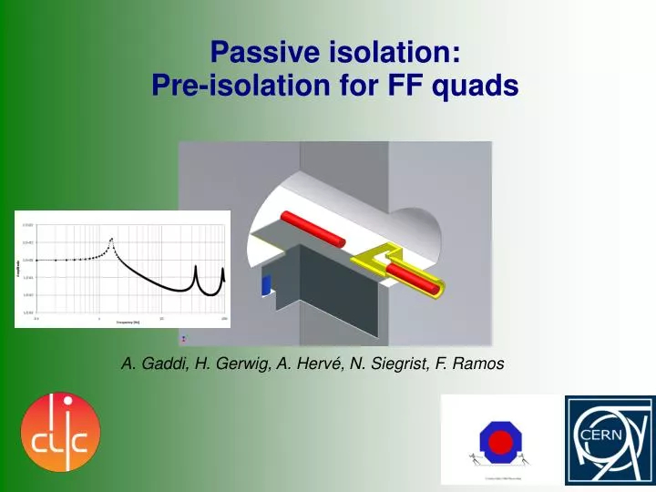
Passive isolation: Pre-isolation for FF quads. A. Gaddi, H. Gerwig, A. Hervé, N. Siegrist, F. Ramos. Retrospective view.

E N D
Passive isolation: Pre-isolation for FF quads A. Gaddi, H. Gerwig, A. Hervé, N. Siegrist, F. Ramos
Retrospective view. In the first CLIC MDI layout (legacy of ILC MDI), the QD0s were supported by the detector, or by a pillar on the detector moving platform. However it became clear, after the measuring campaign at CMS, that the vibrations generated by the detector itself would make impossible to achieve the stability requirements given for the FF magnets at CLIC. Measurements done at CMS courtesy EN-MME/CERN
Scope of work. Try to attenuate, at its source, ground motion vertical excitations, in the range 1 – 20 Hz, to make life easier to the following stabilization systems. Objective. • Stabilize FF magnets to better than 1 nm (rms) at 4 Hz, • using an integrated approach of three systems, each one • with its dynamic range and frequency response: • Passive pre-isolator • Active mechanical stabilization • Beam-based stabilization
Stabilization block diagram. X – ground motion Ki – isolator transfer function D – external disturbances else than ground-motion W – white noise on beam position DY – beam position signal from B. Carron
Pre-isolator – How does it work ? + Low dynamic stiffness (k) mount natural frequency around 1 Hz Acts as a low-pass filter for the ground motion (w) Large mass (m) between 50 and 100 tons Provides the inertia necessary to withstand the external disturbances (Fa), such as air flow, acoustic pressure, etc.)
Where does it fit ? Ideally located at the end of the machine tunnel, just in front of the detector, on both sides. drawing by N. Siegrist
How can it be realized ? QF1 Walk-on-floor QD0 QD0 support tube Mass Elastic support conceptual design
More in details : Accelerator tunnel QD0 SD0 MULT QF1 SF1 Detector side Pre-isolator slab
FE Model Layout. Lumical Beamcal QD0 SD0 MULT QF1 SF1 • Things missing in the model: • Pre-alignment mechanics • Final doublet’s geometries (using, for now, 3-D point masses with estimated inertias) • Final doublet’s supporting structures (girders, etc.) • Pre-isolator’s supports (using , for now, 1-D springs with appropriate stiffness)
Response to excitation in the vertical direction. 1 Hz 51.2 Hz Good performance above the first resonance peak 6
Response to excitation in the horizontal directions. There is a good decoupling between horizontal & vertical directions 7
Random vibration response. Vertical ground motion at CMS. 11
Random vibration response. 2.2 nm 0.1 nm Vertical ground motion at CMS. 4 Hz Reduction in r.m.s. displacements by a factor 20 above 4 Hz 12
Tilting mode Vertical mode Horizontal mode
Experimental set-up – Why ? The idea is promising, but... Is the system’s performance amplitude dependent ? How will it react to different noise sources, else than micro-seism ? What about energy loss mechanisms (friction...) ? What performance can we expect ? We have built a prototype to try to answer to these questions. Although rather different from the reference design, it will serve to validate the idea of having a low-frequency mechanical filter in front of the FF stabilization chain.
Experimental set-up – How ? The prototype needs to be: Simple to design/build/assemble Easy to “debug” & tune Cheap Frictionless pivotal joints Proposal: 40 ton mass supported by 4 structural beams acting as flexural springs
Experimental set-up – Expected performance Performance in ideal conditions (ground motion only). 1.55 Hz CMS floor @Pre-isolator Transmissibility Displacement P.S.D. 2.2nm at CMS floor 15x 0.15 nm at Pre-isolator Integrated R.M.S. Displacement plots by F. Ramos
Example of pre-isolator application in industry. Vibration isolation system at the Centre for Metrology and Accreditation – Helsinki, Finland 4 independent seismic masses (3x70 ton + 1x140 ton) 0.8 Hz pneumatic vibration isolators (“air springs”)
Future plans. • A passive low-frequency pre-isolator has been proposed as a support for the FF magnets. It can be integrated at the interface between the machine tunnel and the detector cavern. • This pre-isolator will constitute the first “layer” of the stabilization chain. • This concept has already been used in other industrial and research facilities. • Experimental tests will be performed to understand how the system behaves in “real life” conditions (no simulation can accurately take into account all these effects). A simple and relatively inexpensive experimental set-up has been conceived and built. Measurements are under way. • Further studies are necessary to integrate the pre-isolator with the civil-engineering and the other MDI systems (pre-alignement, FF magnets, forward detector region, beam-pipe, etc…)
Further considerations. Supporting the FF quads (and in particular QD0) from the tunnel sets some parameters that seem to be difficult to be met with a conventional design of the tunnel-experiment cavern interface, specially for what concerns the civil engineering. What counts to maximize machine luminosity is the relative alignment of the two QD0s, rather than their absolute position. We shall profit of the relatively short distance between QD0s, to try to mechanically link them through a rigid structure that bridges the gap between the two tunnel ends. This would also increase the coherence of low frequency seismic waves across the UX cavern.
Coherence of seismic vibration important for QD0 relative displacement. Integrated RMS (nm) of relative and absolute motion above 1Hz with a rigid fixation. B.Bolzon, march 2009 Measurements have been planned at CMS site, where a 2.25m thick reinforced concret slab, long several tens of meters, and supported by pillars with foundations into the rock, would be the design reference. We aim to understand if a similar design, in the CLIC experiment cavern, would be beneficial for the FF stabilization at low frequency.
Conceptual design: the Quads’ bridge. FFQ stabilization & alignment Main linac Tunnel floor Pre-alignment & stabilization Quads-bridge The design has evolved from a first sketch, aiming to provide the same foundations for the couple of FFQ, to a more complex design that includes a low-frequency vertical pre-isolator.
Conceptual design: the Quads’ bridge + the pre-isolator. FFQ stabilization Main linac Tunnel floor FFQ pre-isolation & alignment Pre-alignment & stabilization Quads-bridge The main linac elements are aligned and stabilized on their girders. The FF quads are mounted inside a supporting tube, the stabilization is located inside the support tube. The FF quads pre-alignment is done by positioning the support tube, via the low frequency pre-isolator. The FF bridge has the function of extending the tunnel concrete slab from one side to the other of the experimental cavern.