Download
1 / 59
590 likes | 720 Views
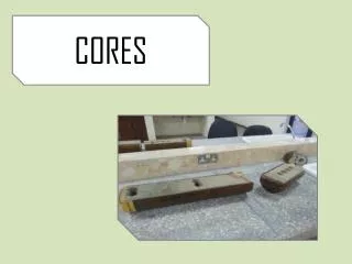
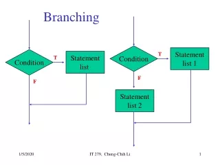
Extracting Branching Object Geometry via Cores. Doctoral Dissertation Defense Yoni Fridman August 17, 2004 Advisor: Stephen Pizer. Outline. Motivation, Background, and Thesis Statement Cores in 3D Handling Branching Objects with Cores Ends of Cores Evaluation and Results

E N D
Extracting Branching Object Geometry via Cores Doctoral Dissertation Defense Yoni Fridman August 17, 2004 Advisor: Stephen Pizer
Outline • Motivation, Background, and Thesis Statement • Cores in 3D • Handling Branching Objects with Cores • Ends of Cores • Evaluation and Results • Scientific Contributions and Future Work
Endovascular embolization Courtesy Toronto Brain Vascular Malformation Study Group http://brainavm.uhnres.utoronto.ca/ Aneurysm in a DSA projection image Motivation: Endovascular Embolization • Driving problem: Endovascular embolization of a cerebral aneurysm
Aneurysm in a DSA projection image Axial slice of head MRA data Motivation: Endovascular Embolization • Difficulty: How to guide catheter to aneurysm • In 2D, projection overlap makes geometry of vasculature ambiguous • In 3D, information lost when viewing 1 slice at a time
3D vessel tree representation Axial projection image of head MRA data Goal • Automatically extract representations of anatomic objects from medical images
Tumor in axial slice of abdominal CT data Courtesy Shands Health Care Motivation: Radiation Treatment Planning • Driving problem: 3D radiation treatment planning
Tumor in axial slice of abdominal CT data Courtesy Shands Health Care Goal • Automatically extract representations of anatomic objects from medical images 3D kidney representation
Blum’s medial axis • The medial axis is a formulation that describes objects by focusing on their middles • Can be thought of as a skeleton or backbone • Pioneered by Blum (Blum 1967, Blum & Nagle 1978) for biological structures An object and its medial axis
A synthetic object and its core Overview of Cores (in 2D) • A core is a medial axis of an object at scale (i.e., in a blurred image) • Why at scale? • To reduce image noise • So small indentations and protrusions on the object boundary are not reflected in the core
A synthetic object and its core Overview of Cores (in 2D) • A core is a medial axis of an object at scale (i.e., in a blurred image) • Each location on the core stores orientation and radius information
Cores as Object Representations • An object’s core provides a discrete representation, at scale, of the object • This can be seen by taking the union of disks centered along the core, with the given radii • This representation is computed automatically Recreating an object from its core
Types of Cores • Two mathematically distinct types of cores have been studied: • Maximum convexity cores (Morse 1994, Eberly 1996, Damon 1998, Miller 1998, Damon 1999, Keller 1999) • Optimum parameter cores (Furst 1999, Aylward & Bullitt 2002) • This dissertation deals with optimum parameter cores; details later
Thesis Statement Optimum parameter cores with branch-handling and end-detection provide an effective means for extracting the branching geometry of tubular structures from 3D medical images and for extracting the branching geometry of general structures from relatively low noise 3D medical images.
Outline • Motivation, Background, and Thesis Statement • Cores in 3D • Handling Branching Objects with Cores • Ends of Cores • Evaluation and Results • Scientific Contributions and Future Work
Core Computation • Initialize a medial atom and place a derivative of a Gaussian at the tips of two spokes • Optimize the derivative of Gaussians’ fit to the image by varying location, radius, and orientation • Take a step forward and iterate Computing the core of a synthetic object
Cores in 3D – Slabs and Tubes • Cores of 3D objects are generically 2D (sheets). Objects represented by 2D cores are called “slabs” • Special case: Cores of tubes are 1D (curves)
A medial atom m = (x, r, F, q) is an oriented position with two spokes. In 3D (Morse 1994, Fritsch et al. 1995, Pizer et al. 1998, Furst 1999, Pizer et al. 2003) x is its location in 3-space r is its radius, or the length of two spokes, p and s F is a frame that defines its orientation b is the bisector of the spokes q is its object angle s q b x r Medial atom geometry p What is a Medial Atom?
I constrain q to p/2, so m = (x, r, F) This improves the resistance of core computation to image noise It is also less natural and affects core computation in other ways I quantify these effects in the dissertation and show that the constraint is beneficial overall s q b x r p My medial atom geometry My Medial Atoms
What is the Medialness of a Medial Atom m? • Medialness M(m) is a scalar function that measures the fit of a medial atom to image data • A kernel K(m) is created from m by placing two directional derivatives of volumetric Gaussians, one at each spoke tip, with the derivatives taken in the spoke directions • M(m) is then computed by integrating image intensities as weighted by K(m) s x p
Maximizing Medialness • Given an approximate atom m = (x, r, F), find x, r, and F that maximize M(m) • Let x = (s, t, u) and F = (az, alt, j) • u is in the spoke direction and (s, t) span the normal plane • az and alt are the azimuth and altitude of b, j is spin about b • Maximize with respect to position and then parameters: • This defines the optimum parameter cores I use
2D core of a kidney Core-Following • Now we need to follow a 2D sheet – can’t simply step forward • Rather, march along a grid Following the 2D core of a slab in 3D
Core-Following • I add two features to core-following that improve its resistance to noise: • When optimizing medialness, I penalize significant changes in radius and/or orientation between neighboring atoms • I compute the core at a coarse sampling (taking large steps between atoms) and then refine the sampling Refining a core
Computing the core of a tube Cores of Tubes • Cores of tubes are computed using medial atoms with a set of (8) concentric spokes • The resulting core is a curve • Problem: Euclidean optimization must cover 2 dimensions, not 1 • Solution: Pick any 2 directions that span normal plane to core, e.g., 2 orthogonal spokes • These cores are more noise-resistant than cores of slabs
Outline • Motivation, Background, and Thesis Statement • Cores in 3D • Handling Branching Objects with Cores • Ends of Cores • Evaluation and Results • Scientific Contributions and Future Work
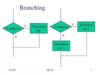
Core-following (in cross-section) Cores of separate branches (in cross-section). q p/2 Problem: Cores Don’t Branch • Problem: Cores don’t branch, so what happens when a core reaches an object bifurcation?
Jumping to cores of new branches Cores of separate branches (in cross-section). q p/2 Solution: Jump to New Cores • Solution: Stop following the core when it reaches an object bifurcation and jump to the new core(s) • One for a slab, two for a tube
Corner Detection • Apply an affine-invariant corner detector to the image: IuuIv2 • v is the gradient direction and u is the first eigenvector of the Hessian in the normal plane to v
A projection image Application of the corner detector Maxima of cornerness Corner Detection • Apply an affine-invariant corner detector to the image: IuuIv2 • v is the gradient direction and u is the first eigenvector of the Hessian in the normal plane to v
Core-following A projection image Application of the corner detector Maxima of cornerness Corner Detection • A spoke tip located at a maximum of cornerness indicates a potential object branch
Maxima of cornerness; red indicates false positive Rejection of False Positive Branches • Maxima of cornerness can also be false positives • For example, bends in the object
True branch False positive branch Maxima of cornerness; red indicates false positive Rejection of False Positive Branches • I reject false positives using combinations of heuristics, e.g., non-increasing radius along the core
Re-seeding cores of new branches Re-seeding Cores Along New Branches • Predict the locations and parameters of the new branches using geometric information from the computed core • Prediction need not be accurate
Outline • Motivation, Background, and Thesis Statement • Cores in 3D • Handling Branching Objects with Cores • Ends of Cores • Evaluation and Results • Scientific Contributions and Future Work
Blood vessel with an implicit end DNA with explicit ends Types of Object Ends • I consider two types of object ends: • Explicit ends, where an object is capped • Implicit ends, where an object narrows until it is indiscernible in the image
Blood vessel with an implicit end DNA with explicit ends Core Termination • Case 1: Stop following a core at an object end • Case 2: Stop following a core when there is not enough evidence that you’re on an object
Core Termination • Use local statistics on medialness values to determine when we’ve lost track of the object • At each step of core-following, create a set S of randomly positioned and oriented medial atoms (yellow) in a region surrounding the current atom, m0 (blue) • Compute the medialness value of each atom in S • m0 is valid iff
Outline • Motivation, Background, and Thesis Statement • Cores in 3D • Handling Branching Objects with Cores • Ends of Cores • Evaluation and Results • Scientific Contributions and Future Work
Demonstration: Core of a Kidney Core of a kidney Surface implied by the core
Demonstration: Core of a Kidney and Renal Artery Cores of a kidney and adjoining renal artery Surfaces implied by the cores
Axial, sagittal, and coronal MIP views of 3D head MRA data Demonstration: Cores of Blood Vessels Surfaces implied by cores of blood vessels
Analysis of the Effects of Object Geometry on Cores • Using synthetic images (with known truth), I analyze the effects of object geometry on cores • For tubes: Width, bending, branching angle, branch size, rate of tapering at ends • For slabs: Rate of narrowing, bending, branching angle • This analysis provides: • Validation of my methods • The ability to predict performance on new objects and images • A better understanding of the behavior of cores
Tube Width • Results: • Success of tubular core-following is related to object width and inversely related to image noise • In MR, tubular core-following is reliable down to tubes of diameter 1 voxel
Tube Bending • Results: • Curvature and torsion are not a limiting factor in tubular core-following • Cores of sharply curved tubes can be followed by decreasing step size
Tube Branching Angle • Results: • Tubular branch-handling is reliable in low-noise images regardless of branching angle • In ultrasound, failure rates were ~20% but all failures were false negatives; there were no false positives
Tube Branch Size • Results: • Tubular branch-handling deteriorates when one branch is significantly narrower than the other, particularly in noisier images
Core-termination errors Tube Rate of End Tapering • Results: • Core-following does not continue past tube ends • Core-following stops near tube ends in low-noise images, stops earlier with increased noise
Slab Rate of Narrowing • Results: • Success of slab-like core-following is inversely related to both narrowing angle and image noise • Medialness is proportional to the cosine of the narrowing angle • Results are the same whether the object narrows or widens in the direction of core-following
Slab Bending • Results: • Sharply bent slabs can be followed better by decreasing step size (like tubes) • Failures occur occasionally (4% failure rate) due to intra-object interference (unlike tubes)
Slab Branching Angle • Results: • Success of slab-like branch-handling is related to branching angle and inversely related to image noise • All failures were false negatives (like tubes)
Outline • Motivation, Background, and Thesis Statement • Cores in 3D • Handling Branching Objects with Cores • Ends of Cores • Evaluation and Results • Scientific Contributions and Future Work