Download
1 / 21
210 likes | 340 Views
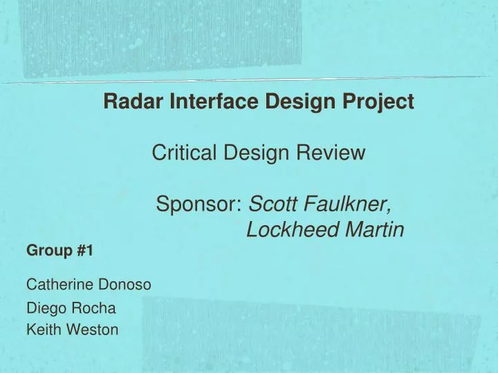
Radar Interface Design Project Critical Design Review Sponsor: Scott Faulkner, Lockheed Martin. Group #1 Catherine Donoso Diego Rocha Keith Weston. Overview. Lockheed Martin sponsored project Advisor is RF Engineer, Scott Faulkner

E N D
Radar Interface Design ProjectCritical Design Review Sponsor: Scott Faulkner, Lockheed Martin Group #1 Catherine Donoso Diego Rocha Keith Weston
Overview • Lockheed Martin sponsored project • Advisor is RF Engineer, Scott Faulkner • Power Supply (PS) for transceiver in Joint Air to Ground Missile (JAGM) seeker • PS must include control unit • PS system must generate specific voltages • PS system must use power sequencing
Goals • Provide solutions to the next generation transceiver power supply design flaws by using innovative ideas • Low EMI • Low thermal characteristics • Smaller circuit card than used before • Find alternative parts utilizing new technology • Provide FPGA loads for future use
Requirements • Lowest EMI possible • Lowest possible power • No heat sink available directly on board, only for system • limited airflow • Preferrable non-Rohs Compliant
Specifications • 32V, 1.5V and 3.3V provided • 3W dissipation for each part • Preferable military grade temperature, -55 to +125 • 6 sq. in board, any shape • High power architecture • +6V • load- less than 50% duty cycle and applied no longer than 100us • pulse repetition rate from 1 to 100 kHz • Low power architecture • load-continuous • -4V, +6V, +9V • FPGA • Power sequencing--4V,+6,+9,+6(high)
Power Sequence • Power UP sequence • -4V, +6V(low), +9V, +6V(High) • exact opposite for power down • SWPS for both high power and low power uses PGOOD pin to send high or low signal to FPGA • FPGA will send signal at least 2.5V to RUN pin to turn ON/OFF SWPS • LDO and charge pump send Vout signal to ADC onboard FPGA • FPGA will send signal to pull up or down SHDN pin to turn ON/OFF parts, must use pull-up resistor. probably transistor for switch • Failure Mode • FPGA must power down all power supplies in exact opposite order
Noise Consideration and Solution • Power supply to transceiver must have clean signal as to avoid possible malfunction because of noise • Must use low noise parts • Difficult to use low noise parts in a power supply-many parts use switching to step-down voltage • Challenge-avoid noisy parts or isolate noisy parts from transceiver • Use filtering • Use mu-metal for magnetic shielding
Tjamax = 150 degrees celsius • Tamax = 59 degrees celsius (found from voltage values given max. Tjamax) • [Iout*(Vin-Vout)] + (Ignd)Vin. Ignd can be found from the graph below. • Very important to narrow the delta between Vin and Vout. SWPS needs step-down voltage as much as possible • SWPS heat dissipation not as severe as LDO Temperature Consideration
Low Power Design • SWPS: LTM8032 • was LTM4612 • low noise • smaller than other models • handles large step-down delta • LDO: LTM1963 • heat dissipation • used as filter • Charge pump: LT1054 • was LT3704 and ripple attenuator • inverts • steps down • small • least noisy of power supplies that invert
Simulation and Experimental Noise Results • SA proved low noise for SWPS,8032 • LTSpice Simulation proved no noise for LDO • LDO useful as a filter
Board Space Consideration and Challenge • Only 6 sq. in., or 3850 sq. mm. in rectangular shape • Power supply requires multiple parts for proper function • Now, main parts occupy 2950 sq. mm. • Parts will be installed only on topside • Est. # of layers is 5-6 • A couple signal layers will be needed to support amount of traces on small surface area for large # of parts • What can be eliminated? Replaced?
Proving the Design • Will not be installed in missile seeker, therefore needs to be proven to work outside of actual system • Mock loads must be created to effectively test power supply • High power architecture will have separate test card • Prototype only purpose, test card will be implemented on same board • Low power architecture will have onboard test card • Logic analyzer used to time power sequence
High Power Section • Process power as required by the load. • Efficiency must fit in the 90 percentile range. • Meet power sequencing. • Meet EMI requirements. • Testing prototype to debug and prove its functionality.
6XMIT Power Supply • 6XMIT will drive the transceiver with load durations ranging from 1k Hz to 100k Hz with a duty cycle no greater than 50%. • 6XMIT 6 VDC @ 11 Amps peak 3% Regulation 1 mV noise. • Implementation of DC/DC converters turns out to be a must in order to meet specs.
LT uModule Family • To facilitate switching power supply Linear Technology has designed 8 dc/dc uModules. • LGA package for these family has been designed with very low thermal resistance thus increasing heat dissipation. • The ultralow noise design has the lowest EMI for DC/DC converter modules.
LTM4612 • 5V to 36 V input voltage range. • 5A DC, 7A peak output current. • Parallel/ Current sharing • Voltage and current protection • Programmable soft-start
Efficiency • Theoretically dc/dc converters are capable of achieving 100 % efficiency. • The LTM4612 ultra-low noise dc/dc buck converter can achieve efficiencies up to 92 %.
Paralleling LTM4612 • Polyphase configuration lowers ripple. • Spreading the spectrum lowers EMI • Current sharing allows converters to be paralleled
Spreading Spectrum Frequency Spectrum using technique Frequency Spectrum without using technique
Testing Prototype TI 2808 DSP Familiarity with 2808 DSP board facilitates test set up. PWM pins have been coded to generate waveforms that can range between 1kHz to 100kHz with a duty cycle that can be varied from 0 to 50%. 200kW resistor load bank available for testing.