Download
1 / 15
200 likes | 440 Views
Plastic. HPGe. Po čet. NaI(Tl). CZT. Energie [keV]. BGO crystals from Novosibirsk. Gamma rays detectors. NaI(Tl) detector for satellite Fermi. 1) Comparative characteristics of detectors 2) Scintillation detectors 3) Semiconductor detectors 4) Crystal diffraction spectrometers.

E N D
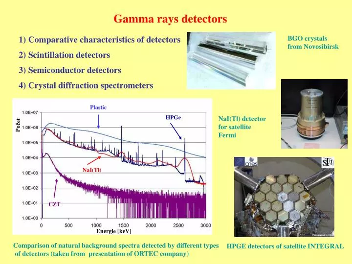
Plastic HPGe Počet NaI(Tl) CZT Energie [keV] BGO crystals from Novosibirsk Gamma rays detectors NaI(Tl) detector for satellite Fermi 1) Comparative characteristics of detectors 2) Scintillation detectors 3) Semiconductor detectors 4) Crystal diffraction spectrometers Comparison of natural background spectra detected by different types of detectors (taken from presentation of ORTEC company) HPGE detectors of satellite INTEGRAL
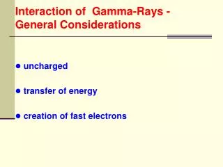
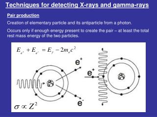
Comparative characteristics of detectors Sensitivity – capability to produce measurable signal for given type of particle and energy. Depends on: 1) cross-section of ionization reactions, photon reactions, ... 2) detector mass, its construction 3) detector noise 4) thickness and type of material surrounding sensitive detector volume Response – relation between particle energy and detector output (total charge or current amplitude of pulse). Response functionF(E,E´) - spectrum S(E´) of monoenergetic beam is observed by detector as complicated function. Usually near to Gauss function with tail to lower energies. Measured distribution of pulse amplitude P(E): E– energy at measured spectrum,E´-initial energy Time response – time of detector signal creation Pulse form – detector signal shape leading edge, declining (even more components) fast component, slow component
Death time – time needed for creation and analysis of detector signal. 1) detector is not sensitive 2) Detector is always sensitive – „pile-up“ is created – amplitude superposition Assumption: death time τ is constant: Case 1 (death time is not extended): Real number of particles: NS = mT = k + mkτ m – real countrate, T – time of measurement, k – number of registered cases Dead time and its influence Real count rate: Case 2 (death time is extended): Distribution of intervals t between signal arrival: then probability that t > τ: and relation between registration number k and real count rate m is:
Detection efficiency – ratio between number of detected particles and number of particles emitted by source – absolute efficiency. It consists of intrinsic efficiency εVNIand geometrical efficiency (acceptance) εGEO: ε = εVNI·εGEO Standard – line 1332 keV of 60Co It is determined also relatively – detector comparably to standard (NaI(Tl) with sizes 7.627.62 cm) in given geometry ( - distance 25 cm) εNaI = 0,12 % Ratio between peak and Compton background – for gamma ray detectors – ratio between maximal amplitude in peak 1332 keV and mean value in the region 1040 – 1096 keV Energy resolution – the smallest distinguishable energy difference ΔE between two near energies. Monoenergetic beam → ideally δ-function – practically peak with finite width (mostly Gauss shape). Resolution is presented in the form of full width at half maximum – FWHM). Relative resolution ΔE/E in [%] is also used. differences from Gauss shape are given by: FWTM – width in 1/10 of high FWFM – width 1/50 of high Gauss: FWTM/FWHM = 1.82 FWFM/FWHM = 2.38 Also other distributions, asymmetries, electrostatic spectrometer – Lorentz shape
FWHM – energy resolution: (It is valid for scintillation, semiconductor, gas detectors) Number of created charge carriers, photons …: where eS is mean energy needed for creation of charge carrier or photon Ionization and deexcitation – Poisson distribution → standard deviation: Relation between FWHM and σ for Gauss shape: FWHM = 2.35 ·σ Detector absorbing only part of energy: Deposited energy E freely fluctuate → Poisson distribution is valid: Detector absorbing total energy (photon detectors): Deposited energy is fixed finite value → Poisson is not valid, correction introduces Fano: where F – Fano correction Relative energy resolution:
Comparison of absolute and relative resolution for scintillation and semiconductor detectors FWHM value is influenced by another factors: absorption of charge carriers, photons properties of electronic …. In the case of independent contributions: (ΔE)2 = (ΔETN)2 + (ΔEPN)2 + (ΔEELEK)2 + … Time resolution – the smallest resolvable time difference – definition similar to energy resolution Space resolution – the smallest resolvable space difference – definition similar to previous
Gauss shape before irradiation Shape after irradiation Tolerance to radiation damages– irradiation → damages, crystal lattice defects, bugs less sensitive – liquid and gas detectors more sensitive – scintillation and mainly semiconductor detectors Illustration of downgrade of HPGE detector of INTEGRAL satellite after irradiation (A.Thevenina report) Detectors work in strong radiation field During experiments on accelerators Sometime gradual regeneration is possible, HPGe detector is possible to regenerate after warming
Scintillation detectors Scintillation detector: 1) Scintillator 2) Photomultiplier + magnetic shielding (or photodiode) 3) Base Ionization radiation passage → excitation of atoms a molecules deexcitation → energy → light production - luminescence Information: 1) Energy 2) Time – they are fast 3) Particle identification from pulse shape Fluorescency– fast energy conversion to light 10-8s Phosphorescency- delayed energy conversion to light μs – days – longer λ Properties of photomultipliers, photodiodes, avalanche photodiodes – see literature
Discharge has exponential behavior: One-component Binary: τR – fast component, τP – slow component Example of signal shape of binary scintillator Požadavky na scintilator: 1) High efficiency of excitation energy conversion to fluorescent light 2) Conversion should be linear 3) Transparency for fluorescence light (light emission should be in different range than light absorption 4) Fluorescent spectrum should be compatible with photomultipliers 5) Short decay constant 6) It should have good optical properties and easily machinable 7) Index of refraction should be near to n = 1.5 (glass) – good crossing passage of light to photomultiplier
Organic scintillators:1) Organic crystals – anthracene, stilbene 2) Liquid organic scintillators very resistive against radiation damage, measured radioactive substance can be part of detector 3) Plastic scintillators – very fastτ ~ 2 ns, NE111:τleading edge= 0.2 nsand τ = 1.7 ns lower Z → small σ for photoeffect, Compton scattering dominates, addition of heavy element admixture (Pb) → increasing of photopeak, decreasing of light output Inorganic scintillators:are slower, higher Z → more suitable for gamma radiation, CsI(Tl), NaI(Tl) (is hygroscopic), BGO (Bi4Ge3O12), BaF2,PbWO4 BGO, BaF2, PbWO4very useful for high energy gamma BaF2 very fast (fast component), two components ρ[g/cm3]eS[eV]τ[ns] Anthracene ~0,8 60 30 Plastic (NE111) ~1.2 100 1.7 NaI3.67 25 230 BGO 7.13 300 300 BaF2 4.89 125 0.6 (fast c.) 600 (slow k.) Limiting theoretical resolution, without inclusion of influence of electronic and charge carrier trapping Fano coefficient is for scintillators F ~ 1
TAPS and ALICE photomaterials BaF2 crystals of photon spectrometer TAPS ultraviolet components λ=220nm and λ=310 nm Crystal PbWO4 of high energy photon spectrometer ofproject ALICE, blue λ= 420 nm andgreen λ= 480-520 nm
Semiconductor detectors Very common: HPGe (earlier Ge(Li)) – need liquid nitrogen cooling Si – for low energy range Newer and up to now more special: CdTe, HgI2, CdZnTe (CZT) – up to now for lower energies, cooling is not necessary, eS ~ 4.4 eV Ge, Si – four valence electrons – electron release (its transposition from valence to conduction band) → creation of hole and free electron Impurity with 3 valence electrons – electron recipient → →hole predominance → semiconductor of p type Impurity with 5 valence electrons – electron donor → → predominance of electrons → semiconductor of n type Ge(Li) detector – 1012 impurity atoms per cm3 HPGe – 109 impurity atoms per cm3 WWW pages of W. Westmaier Prevention of thermal production of electron-hole pairs → temperature 77 K Capture and recombination on dislocations and impurities HPGe detector placed inside Shielding lead box
Basic semiconductor properties: forT=77 KSi Ge Z 14 32 Atomic mass 28.09 72.60 Density ρ [g/cm3] 2.33 5.33 Energy gap [eV] 1.1 0.7 Electron mobility μe[ 104cm2/Vs] 2.1 3.6 Hole mobility μd[104cm2/Vs] 1.1 4.2 eS [eV] 3.76 2.96 Fano coefficient F ~ 0.09 ~ 0.06 ve = μe·E vd = μd·E Voltage on detector more than 1000 V Small pulses → necessity of preamplifier: detector → premaplifier → amplifier → ADC → analyzer, computer Position sensitive HPGe segmented detectors are developed by LLNL (Californian University) its WWW Technical details – see recommended literature
Parameters for 60Co line with energy 1332 keV Relative efficiency To the standard (NaI(Tl)): 10 – 70 % (εNaI = 0.12 % εGEO ~ 0.58 %εVNI ~ 20 % ) peak/compton: 1:30 až 1:60 Resolution: FWHM 1.7 – 2.3 Peak shape: FWTM/FWHM ~2.0 (Gauss 1.82) FWFM/FWHM 2.65 – 3.00 (Gauss 2.38) ΔEΣ2 = ΔETN2 + ΔEELEK2 + ΔEPN2 ΔETN – intrinsic uncertainty (carrier creation) ΔEELEK – uncertainty given by electronic ΔEPN – uncertainty given by electron and hole recombination and capture Low energies – Si and thin HPGe detectors, beryllium window High energies - HPGe with large volume, aluminum window longer (6 μs) or shorter (2 - 4 μs) time constant of amplifier Limiting theoretical resolution, without inclusion of influence of electronic Energy measurement accuracy up to order eV Massive practical usage → many commercially produced types and models
Source Collimator φZ φC φK ΘB Crystal lattice Crystal diffraction spectrometers Consist of 1) crystal lamina (quartz crystal, calcite) 2) detector of X- and gamma rays Characteristic angles influenced on line width φZ – angle of source visibility from crystal φK – angle of collimator visibility from source φC – angle of diffraction line FWHM ΘB – Bragg angle Angular FWHM φ of intensity afterwards is (for small values of all angles in radians) φ2 ≈ φZ2 + φK2 + φC2 Detector Different crystal geometries: Plane crystals Curved crystals Different configuration: with one crystal Θ = ΘB with two crystals Θ = 2ΘB R – angular resolution Example of measurement accuracy: 169Yb → 169Tm line 63 keV – E = 63.12080(16) keV Necessity to include influence of nucleus reflection during photon emission and accuracy of energy standard determination