Download
1 / 12
120 likes | 218 Views
MICE magnet positional tolerances when assembling the cooling channel. Tim Hayler STFC. MICE NOTES. 229 Alignment Errors on Emittance Measurements for MICE David Forrest, F.J.P. Soler deals with spectrometer alignment (step VI, flip, 200 MeV/c ) - gives tolerance of order 10 mm, 3 mrad

E N D
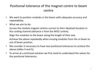
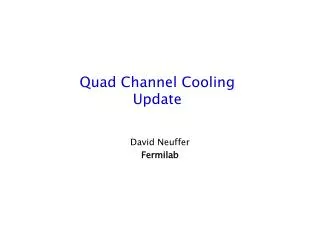
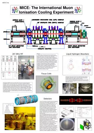
MICE magnet positional tolerances when assembling the cooling channel Tim Hayler STFC
MICE NOTES • 229 Alignment Errors on Emittance Measurements for MICE David Forrest, F.J.P. Soler deals with spectrometer alignment (step VI, flip, 200 MeV/c) - gives tolerance of order 10 mm, 3 mrad • 202 Beamline to MICE Alignment and Matching Tolerance C. Rogers deals with beam alignment to cooling channel (step VI flip 200 MeV/c - gives tolerance of order 2 mm, 10 mrad • 64 Initial study of MICE Magnet Alignment Requirements U. Braver, J.H. Cobb deals with focus coil alignment (step VI, flip, 200 MeV/c) - gives tolerance of order 2 mm, 2 mrad Thanks to Chris Rogers and John Cobb for the information
Conclusion Different studies, all agreeing with a general tolerance of 1 mm, 1 mrad? Does this tolerance simply cover our backs? Can we relax these tolerances for the cooling channel? seems the order of importance is: Tilt angle very important Transverse not so important Longitudinal less stringent again Can we split up the tolerance into these three components?
MICE Hall CSYS y z x
The position of the magnetic axis with respect to a tolerance zone about the nominal axis 1mm Cylindrical tolerance zone of 1mm diameter Magnetic axis of the module Beam Nominal axis Y Reference the MICE hall coordinate system on slide four X Z Projection
The positional tolerance of the magnet centre longitudinally with respect to the nominal centre Downstream Upstream Y Nominal centre Magnet centre y Z X z x ±0.5mm Reference the MICE hall coordinate system on slide four
Table of positional tolerances Potential to relax and split the tolerance zone into tilt and traverse tolerances?
Spectrometer feet locations 1250 Spectrometer foot 2160 The Spectrometer has four feet, in each foot there is a boss that houses a locating pin. The locating pin is threaded into the boss and can be adjusted in height about its nominal position. A hemispherical dome on the end of the pin locates in a similar hemispherical cup on the support frames.