Download
1 / 44
440 likes | 441 Views
This research explores the brightness deterioration of ultra-focused beams due to excess chromaticity and proposes possible solutions for beam emittance dilution. It analyzes the 6D brilliance chart and presents simulations and results from ALADYN and ASTRA.

E N D
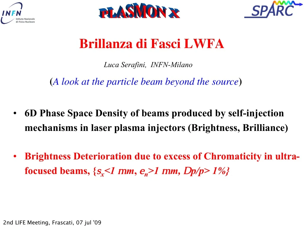
Brillanza di Fasci LWFA Luca Serafini, INFN-Milano (A look at the particle beam beyond the source) • 6D Phase Space Density of beams produced by self-injection mechanisms in laser plasma injectors (Brightness, Brilliance) • Brightness Deterioration due to excess of Chromaticity in ultra-focused beams, {sx<1 mm, en>1 mm, Dp/p> 1%}
Vittoria Petrillo Università degli Studi, Milano (Italy) Alberto Bacci, Andrea R. Rossi, Luca Serafini, Paolo Tomassini INFN, Milano (Italy) Carlo Benedetti, Pasquale Londrillo, Andrea Sgattoni, Giorgio Turchetti Università and INFN Bologna (Italy) Massimo Ferrario INFN-LNF, Frascati (Italy)
1018 1017 AOFEL I [kA] 1016 1015 1014 1013 n[m] Self-Inj SPARX Ext-Inj X-ray FEL @ 1 pC SPARC Photo-injectors The Brightness Chart [A/(m.rad)2]
1017 Bn 1016 1015 1014 Dg/g[0.1%] AOFEL X-ray FEL @ 1 pC Ext-Inj SPARX Self-Inj SPARC The 6D Brilliance Chart [A/((m.rad)20.1%)]
First stage:LWFA with a gas jet modulated in areas of different densities with sharp density gradients.
W0=23 m, T=17 fs I=8.5*1018 W/cm2 , E=2.4 J Aladyn, see C. Benedetti’s talk
Longitudinal phase space and density profile Selection of best part in the bunch: 40 pC in 2 fs (600 nm) projected rms n = 0.7 m <> <>
Best slices Slice analysis: length of each slice
TTFEL scheme proposed by Gruener et al. (T=1.74 GeV, I=160 kA, en=1mm, DE/E=0.1%, sx=30 mm) where an electron beam generated by LWFA in the bubble regime is driven in a static undulator lu=5 mm, lrad=0.25nm, Lsat=5m, trad=4fs, Psat=58 GW,
AOFEL CO2 envelope CO2 focus r m] TiSa envelope TiSa pulse e- beam plasma Lsat=10LG=1.3 mm (=0.002) Z [m]
Thomson Source with LWFA Thomson Source with photoinj.
Slice 8, I=25 kA Equivalent Cathode
Transverse and longitudinale phase and configuration spaces @ 0 cm
Transverse and longitudinale phase and configuration spaces @ 45 cm
ASTRA (A. Bacci) : matching with a triplet • Emittance Dilution due to Chromatic Effects on a beam emerging from a focus of spot size s0, drifting to a distance d
Space charge energy spread No Space charge energy spread
No Space charge No energy spread SPARC beam Space charge energy spread
sp=2 px Den/en=1 en=1 x s0=0.5 after drift d=2 px sp=0.71 Den/en=0.18 en=1 x s0=1.41
Emittance Dilution due to Chromatic Effects on a beam emerging from a focus of spot size s0, drifting to a distance d Valid also for protons/ions SPARC en=1 mm.mrad, s0= 200 m, g=300, Dg/g=0.6%, d=10 m Den =0.005 mm.mrad Self-Inj en=2 mm.mrad, s0= 1 m, g=2000, Dg/g=2%, d=1 m Den =40 mm.mrad
How to measure this emittance blow-up? No trace on beam envelope… energy selection?
Conclusions • Beams produced by Self-Injection in the bubble regime look affected by strong chromaticity: serious emittance dilution after the source, loss of beam brightness • Possible cures: prompt focusing in mm (plasma lenses?), energy selection (charge loss), emittance compensation schemes, adiabatic matching at plasma interface? • Maximum brightness with step downramp density injection (1D mech., localized injection) Needs new targets, shock wave gas jets
Third stage Numerical Modelling First stage Formation of the plasma Formation of the bunch Acceleration stage Transition Plasma-undulator Beam-CO2 laser Interaction FEL instability Genesis 1.3 EURA Prelim. Results with VORPAL J. R. Cary et al. New results by ALADYN, now become our simul. tool Astra Retar Secondstage
Second stage: Transition from the plasma to the interaction area with the e.m. undulator (analysis by ASTRA) With space charge Without space charge
beam plasma acceleration focusing emittance Beam-plasma wavelength betatron length laminarity parameter SPARC 640 m transition spot-size SPARX 580 m AOFEL 3 m Bubble-self.inj. 80-150 m