Download
1 / 60
730 likes | 1.05k Views
Electrical Fundamentals. Board of INSURV on USS Trenton “First Electrified Naval Ship”. REFERENCES. NSTM 300 ELECTRIC PLANT GENERAL NAVEDTRA 14344 ELECTRICIANS MATE NSTM 310 GENERATORS/ CONVERSION EQUIP NSTM 320 DISTRIBUTION SYSTEMS NEETS MOD 14173 INTRO TO DIRECT CURRENT

E N D
Board of INSURV on USS Trenton“First Electrified Naval Ship”
REFERENCES • NSTM 300 ELECTRIC PLANT GENERAL • NAVEDTRA 14344 ELECTRICIANS MATE • NSTM 310 GENERATORS/ CONVERSION EQUIP • NSTM 320 DISTRIBUTION SYSTEMS • NEETS MOD 14173 INTRO TO DIRECT CURRENT • NEETS MOD 14174 INTRO TO AC CIRCUITS
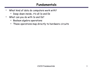
TERMINAL OBJECTIVE DESCRIBE and EXPLAIN the function and theory of shipboard electricity and its role in the electrical distribution system.
ENABLING OBJECTIVES • State the basic units of measure, symbols or abbreviations for various electrical terms. • Define Ohm’s law • State the three requirements for electromagnetic induction • Define the types of AC power • Describe the internal parts of a generator
More Objectives • State the functions of a governor and a voltage regulator • Explain the theory of operation of transformer action • Explain a real ungrounded electrical system • Describe Selective and Selected Tripping
VOLTAGE – “Electrical Pressure” 3 Factors necessary to produce an AC Voltage • Conductor • Magnetic Field • Relative motion between the two
Current - What is it? • Voltage and Complete Path Needed • Movement of Electrons Past a Given Point (Measured in AMPS) • 1 “Coulomb” in 1 sec. past a given point = 1 AMP • Coulomb= 6.28 x 10¹⁸ electrons
“RESPECT…NOT FEAR” • .001 Amps = “Tingling Sensation” (Shock Felt) • .01 Amps = “Clutching Current” • .1 Amps = May be Fatal
OHM’s LAW Voltage = Current * Resistance E=IR or I=E/R R=E/I
In SERIES…the Law Is: • Current (I) is COMMON throughout • Resistance (R) is ADDITIVE • Voltage (E) is ADDITIVE
In PARALLEL, the Laws are Different: • VOLTAGE (E) is COMMON in every branch • CURRENT (I) is Additive • The TOTAL circuit RESISTANCE (R) is LESS than any one Branch!
“Shorts & Opens” • Electrical “SHORT” = Minimal Resistance • Electrical “OPEN” = Infinite Resistance
INDUCTANCE AND CAPACITANCE • INDUCTOR: Opposes CHANGE in CURRENT • (Measured in “Henry’s”) • CAPACITOR: Opposes CHANGE in VOLTAGE • (Measured in “Farads”) • The COMBINED Opposition is called “Reactance” and measured in OHMS
POWER • “RATE at which work is being done” • Power = Current x Voltage • (Measured in WATTS) • FYI: 1 Horse Power = 746 Watts
POWER (Cont) True - Power that actually does work. (KW Meter) Reactive - Power used by reactive elements. (KVAR - not useful) Apparent = combination of Ptrue andPreactive Power.
Power Factor (PF) • Ratio of TRUE Power (Wattmeter), to APPARENT Power (KVA: Ammeter x Voltmeter). • .8 PF is Standard on Naval Ships • Identifies Power Lost due to Reactive Elements • TP = KW = POWER FACTOR • AP KVA
Single Phase Alternating Voltage Frequency = Cycles/sec = Hertz (Hz) One Cycle Voltage Time
Frequency Calculation • Dependant on number of “POLES”, and SPEED of the rotor (prime mover RPM) F = n x s • 120 • F= FrequencyN = Number of Poles • S= Speed (RPM) of Rotor • 120 = standard formula constant
Number and location varies from ship to ship, usually two or more Placed as far apart as feasible Ship’s Service Switchboards
EPCP operation • Remote operations • Allows the operator: • Start and stop generators • Monitor electrical plant • Parallel generators
Ground Detector Lights • Indicates presence of a low insulation resistance • Three lamps and test switch • Normally illuminated • Faulty phase will be indicated by a dark lamp when in test position
Ground Detector Operation • Only works when the test button is pushed • Must see lights flicker when pressing test button • Grounds don’t go through transformers • Light must be “out”
Isolating a Ground WATCH STANDER’S ACTIONS: • OBTAIN PERMISSION FROM EOOW (via CHENG, via CO) • SPLIT ELECTRICAL BUS TO ISOLATE SWITCHBOARD TO LOCALIZE GROUND • RE-PARALLEL ELECTRICAL BUS • SECURE BREAKERS ON AFFECTED SWITCHBOARD ONE AT A TIME UNTIL GROUND GOES AWAY • NON-VITALS FIRST • LIKELY DEVICES - GALLEY EQUIPMENT, EQUIPMENT THAT WAS RECENTLY PLACED ONLINE
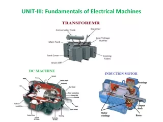
Transformer Theory • Transfers AC Power from one circuit to another by Electromagnetic Induction • FREQUENCY is not changed • No Moving Parts
XFMR Construction • Consist of PRIMARY and SECONDARY Windings • May be “Step-Up” or “Step-Down” • Determined by “Turns ratio” of Primary and Secondary Windings
4000A 750A 100A 15A Fault Ld Ctr SWBD Distr Pnl Source Trips 4th 3rd 2nd 1st Selective Tripping Designed into the system Protective device closest to a fault trips Protects the rest of the system


![FUNDAMENTALS OF ELECTRICAL ENGINEERING [ ENT 163 ]](https://cdn1.slideserve.com/2962351/fundamentals-of-electrical-engineering-ent-163-dt.jpg)