Download
1 / 38
380 likes | 388 Views
Home Brew Multiband Vertical HF Antenna. Kelby Davis AD7VO 2018. Design Objectives. Multi band HF operation Eliminate guy ropes as much as possible Easy set-up and take-down to enable portability for field day Build rather than buy, at lower cost. Complete Installed Antenna.

E N D
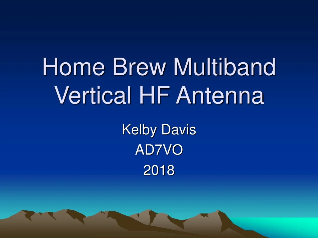
Home Brew Multiband Vertical HF Antenna Kelby Davis AD7VO 2018
Design Objectives • Multi band HF operation • Eliminate guy ropes as much as possible • Easy set-up and take-down to enable portability for field day • Build rather than buy, at lower cost
Full Assembly The radial wire element is connected to the transmission line by a wire from the screw in the bottom of the radial wire clamp to the flange of the SO-239 coax connecter.
Common Mode Currents • Unbalanced antennas typically suffer from common mode current flowing on the outside of the transmission line coax. • A home brew common mode choke was constructed using EMI ferrites salvaged from computer monitor interface cables. • The ferrite cores are type 43 mix. • Three turns of RG-58 coax is all that would fit in these ferrites. • Three turns through two ferrites was repeated three times in series. • An impedance measurement with a Lab grade Vector Network Analyzer indicated excellent choking impedance at approximate 7 MHz and good impedance from 3 MHz to 30 MHz. • This choke eliminated the common mode currents on my coax.
VNA S21 Measurement Yellow trace shows common mode attenuation, Green indicates the phase
Max Gain Fiberglass mast • 2″ OD, 1/8″ Wall, 8 ft. Round Tube $29.95 • 1-3/4″ OD, 1/8″ Wall, 8 ft. Round Tube $24.95 • 1-1/2″ OD, 1/8″ Wall, 8 ft. Round Tube $22.95 • 1-1/4″ OD, 1/8″ Wall, 8 ft. Round Tube $14.95 • 1″ OD, 1/8″ Wall, 8 ft. Round Tube $11.95 • 3/4″ OD, 1/8″ Wall, 8 ft. Round Tube $10.95 ______________________________________________________ • Total $115.70 • The mast will slip fit over a 5 ft. long 1-1/4” galvanized pipe which is driven into the ground. A second pipe supports the radial element. • I used 8 ft. long fiberglass tube sections because I already had them. The tubes are only extended 4 ft. By doing this, the mast will support itself without guy ropes. When the tubes are fully extended, guy ropes are necessary to keep it straight.
Source for Spools *Empty wire spools are purchased on eBay from the vendor “mowfugger” https://www.ebay.com/itm/5-NEW-4-EMPTY-Plastic-Wire-Spools-Bobbins-2lb-wire-spool-CORD-RIBBON-CRAFTS/371958959159?hash=item569a7b4c37:g:FVMAAOSwg3FUg1B4 Or https://www.ebay.com/itm/5-NEW-Empty-Plastic-SPOOLS-Wire-Cord-Ribbon-Craft-1lb-size-New-4-x2-SPOOL/302059554664?hash=item4654270768:g:0sgAAOSwkNZUg0v4 I have used two different versions, one type has a 3” inner spool diameter and the other has a smaller 2” inner spool diameter. The outer flange diameter is the same 4” for both.
Impedance Matching • The desired 50 ohm impedance can be accomplished in two ways… • Make the vertical element a little longer and the radial a little shorter or… • Make the Radial a little longer and the vertical element a little shorter. • The longer vertical element provides a lower take-off angle of radiation more suitable for DX. • Element lengths may need to be adjusted for different locations due to differing ground conditions.
Element lengths, Vertical vs. Radial 19ft Vertical 14ft Radial 14ft Vertical 19ft Radial
Measuring common mode current • A simple meter can be constructed to indicate the presence of common mode currents on a coax transmission line. • A current transformer is constructed with a Ferrite “Snap-it” core such as used on computer cables. (Fair-Rite 0443167251) • The transformer is constructed by wrapping ten turns of 28 gauge insulated wire on one half of the open core. • The signal is rectified by a germanium diode and indicated on a 50 – 100 micro amp panel meter. • A variable resistor provides adjustment for a full scale meter reading of the common mode current. • Avoid metallic support structures in assembling the unit as much as possible.
Meter schematic Cable under test 1N34 diode 1K Potentiometer Fair-Rite 0443167251 Type 43 Snap-it core 50 – 100 uAmp meter .001 A 47 10 turn secondary