Download
1 / 16
180 likes | 371 Views
Effect of Armature Inductance on Commutation – No Load. Consider Coil #2 Induced Voltage changes from clockwise to counter-clockwise as the coil passes from under the South pole, through the neutral plane, to under the North pole. Coil #2 Under the South Pole.

E N D
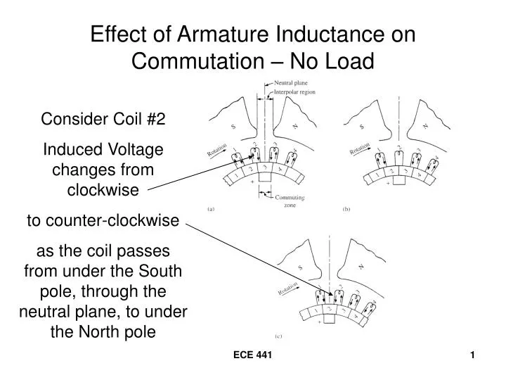
Effect of Armature Inductance on Commutation – No Load Consider Coil #2 Induced Voltage changes from clockwise to counter-clockwise as the coil passes from under the South pole, through the neutral plane, to under the North pole ECE 441
Coil #2 Under the South Pole Clockwise voltage induced in coils under the South pole Counter-clockwise voltage induced in coils under the North pole ECE 441
Coil #2 in the Neutral Plane Coil #2 is shorted out by the brush No voltage is induced ECE 441
Coil #2 Under the North Pole Counter-clockwise voltage induced in the coil ECE 441
Under “Loaded” Conditions Coils #2 and #3 supply current to the load through the commutator bar #3 and the brush to LOAD ECE 441
Coil #2 in the Neutral Plane Current in Coil #2 wants to go to zero, but cannot change instantaneously! ECE 441
Coil #2 Under the North Pole As soon as commutator bar #3 slides off the brush, the current in coil #2 is forced to zero A large emf is induced between commutator bar #3 and the brush, resulting in an “arc” ECE 441
Ideal Commutation For Ideal Commutation, need the coil current in phase with the coil voltage (no delay) ECE 441
Interpoles – Generator Action • Install narrow poles in the Neutral plane • Only the coil undergoing commutation is affected • A neutralizing voltage forces the reversal of current in each coil as it moves through the region ECE 441
Interpoles – Motor Action Connected in series with the armature winding Incorrect polarity makes the sparking problem worse ECE 441
Armature Reaction -- Generator Neutral Plane shifts in the direction of rotation ECE 441
Armature Reaction -- Motor Neutral Plane shifts opposite to the direction of rotation ECE 441
Compensating Windings • Eliminate armature reaction by setting up an mmf that is always equal and opposite to the armature mmf • Connect in series with the armature • Use in connection with interpoles ECE 441
Compensating Windings -- Motor ECE 441
DC Machine with Interpoles and Compensating Windings ECE 441