Download
1 / 34
340 likes | 431 Views
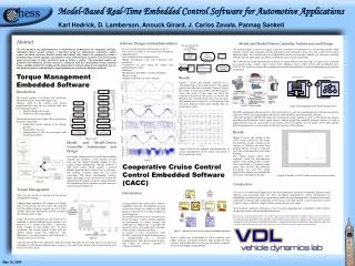
J. Karl Hedrick Carlos Zavala Pannag Sanketi Mechanical Engineering Dept., University of California, Berkeley. Model-Based Control for Automotive Cold Start Applications. 2007 CHESS Winter Meeting. Regulation limit. HC. Cumulative HC amount. 100. Speed. Speed[km/h]. 0. 0. 25. 50.

E N D
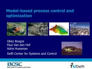
J. Karl Hedrick Carlos Zavala Pannag Sanketi Mechanical Engineering Dept., University of California, Berkeley Model-Based Control for Automotive Cold Start Applications 2007 CHESS Winter Meeting
Regulation limit HC Cumulative HC amount 100 Speed Speed[km/h] 0 0 25 50 75 100 Time[sec] Coldstart Challenges Low emission - Suppressing emissions, especially HC High quality - Driveability : noise & vibration - Robustness against environmental condition and disturbance Less cost - Calibration effort - Design process, especially verification - Computational load - Sensors
Coldstart in IC Engines-The problem • The catalyst is not active below temperatures of around 300C- 400C • Cold Combustion Chambers and poor vaporization in intake manifold • Oxygen Sensor not active at cold temperatures …more than 90% of Hydrocarbon (HC) emissions is produced during the Coldstart Cycle
Model Based Approach to Emissions Reduction during Coldstart • Utilizes formal description of the engine to derive efficient ways of control. • Physical Models. Intuitive representation. • Black box models. Non-physical parameters. • Gray models. Combination of the two above • Motivation - improved control - efficient generation of software - software reusability
Engine Model Catalyst Model Next design iteration Implementation And Testing Model Validation Controller Design Model Based Strategy
Control Oriented Modeling • Simplicity in models is important dx/dt= f(x,u) Lumped Parameter Model (preferably low order ODE) Complex nonlinear system
Engine Subsystems • Manifold Dynamics • Catalytic Converter • Fuel Dynamics • Torque Gen • Raw HC • Exh Temp
Engine Subsystems Modeling General Purpose Engine Modeling • For control of air-fuel ratio, idle speed, models developed ~1980 • Combustion torque generation • Rotational dynamics and time delays • Actuator and sensor dynamics Cold Start Engine Modeling • Air and fuel dynamics • Catalytic converter dynamics • Engine thermal dynamics
Puddle Fuel Dynamics Model • Poor vaporization when air intake is cold
AFR Estimation using Fuel Dynamics Use of fuel-dynamics model to predict AFR. “Fuel Dynamics Model For Engine Coldstart”, Zavala, et.al, IMECE2006-15203, Nov. 2006
Catalytic Converter Model* conversion efficiency map O2 storage dynamics cat. substrate thermal dynamics Qin=hinAin(Texh -Tcat ) internal convection: Qout=houtAout(Tcat -Tamb ) external convection: * [Brandt, Wang, Grizzle, 1997]
Important Elements in a Catalyst Model Heat transfer coefficients of the catalyst
Typical Experimental Catalyst Temperature Profile 350 300 250 200 (C) cat T 150 100 50 0 0 10 20 30 40 50 60 70 80 90 100 Time (s) Important Elements in a Catalyst Model Plateau in the Tcat profile • Due to evaporation of moisture • Starting point can be detected (~470 C) • For finding the end of plateau, various methods – adaptation, offline calculation of evaporation heat* *[Sanketi, Zavala, Hedrick et al., AVEC ’06]
Raw HC and Texh Modeling • Simple, intuitive models • Suitable for controller design • Inputs chosen based on physics and experimental data • AFR, Spark directly affect combustion • Changes in RPM affect the combustion quality • Sum of first order linear systems • such behavior observed in exp • Saturations, offsets on inputs exist • Use of Least Squares to find parameters
y u ? Plant Control Design Once the plant is defined, the synthesis of a controller should considered : • Performance requirements • Uncertainty • Nonlinearities • Actuator bandwidth • Sensor noise • Disturbances
Lab Engine Interface Spark Timing Variable Valve Timing Throttle angle Amount of Fuel Sensors Inputs Texh sensor AFR sensor HC Analyzer Tcat sensor Catalyst model AIR AIR Tailpipe HC estimation Catalyst temperature estimation Air induction dynamics Performance outputs Engine out HC estimation Fuel induction dynamics Thermal model HC formation model In cylinder pressure measurement
Two control approaches: mean value-hybrid MeanValue Hybrid Plant model Control Objectives Plant model Control Objectives Design Hybrid Controller Design Design Controller Design Controller 1 Controller n … Controller Controller j Controller k Operation Operation Controller … Controller i
Trying out different profiles • Different HC desired and Tcat profiles Desired Profiles
analysis of complex embedded systems software assurance through modeling in all phases of software development process Handling hybrid system analysis Software timing analysis Model-Based Integration of Embedded Systems The complexity of automotive systems demands the use of more sophisticated tools for control software verification:
Why hybrid models? • Advantages • It accounts for continuous dynamics and discrete events. • It offers a more detailed description compared to mean-value models. • Disadvantages • No analytic solutions for stability analysis • More complicated than mean-value models. • Analysis tools still in development
Engine Model • Mean Value models of Intake air flow and manifold air mass. (continuous dynamics). • Air and fuel flowing into cylinder calculated for each combustion cycle.(Discrete quantities). • Strokes of engine considered as discrete events using finite state machines (FSM:hybrid) . • Torque and pollutants modeled for each combustion cycle. (continuous functions based on events: hybrid).
Controller Verification of Hybrid Systems • Question of stability and evolution of the states • Model simulations cannot cover all possible trajectories inside a set • Reachability analysis • Tells you how your state space will behave with time starting given a set of initial conditions and bounds on inputs • Very useful in verifying the controller performance
Example Hybrid Controller • Cumulative tailpipe HC function of both raw HC and catalyst efficiency • Trade off exists between the two objectives • A high level hybrid controller to exploit the trade-off
Control Hierarchy The hybrid controller switches between the Tcatand HC dynamic surface controllers The low level Texhand AFR controllers use spark timing and fuel injection rate as the inputs respectively The Tcatand HC dynamic surface controllers use Texh and AFR respectively
Hybrid Controller Modes Helps fast catalyst light-off Helps keep the raw emissions low
Reachable sets Test: starting from a safe set, remain in the set. Set of Initial states Target Set Backwards Reachable Set Forward Reachable Set Test: starting from an unsafe set, never touch the set of initial conditions
is the set of states for which, for all control actions, there exists a disturbance action which can drive the system to in at most Target Set G(0) Backwards Reachable Set G(t) Backwards reachable set calculation Say, the controlu wants to keep the system away from target set of states whereas the disturbance d tries to drive the system to the target set G(0). Now how to compute this set? Turns out that it can be computed by solving a HJI PDE Ref. Tomlin et.al
Reachability Analysis of Coldstart Controller* *[Sanketi, Zavala, Hedrick]- IJC, 2006 Backwards Reachability
Conclusions • Hybrid modeling helped to achieve a more detailed description of engine operation • Hybrid control gave the chance to explore the tradeoff of hydrocarbon emissions level and catalyst light-off. • Hybrid modeling is a useful tool for coldstart analysis.
Future of coldstart control • Fewer experiments for model validation. • Closed-Loop control design • Easy adaptation to new engines. • Automated code generation. • Automated software validation and verification. • Use of AFR and HC production sensors and/or model based observers.