Download
1 / 15
150 likes | 237 Views
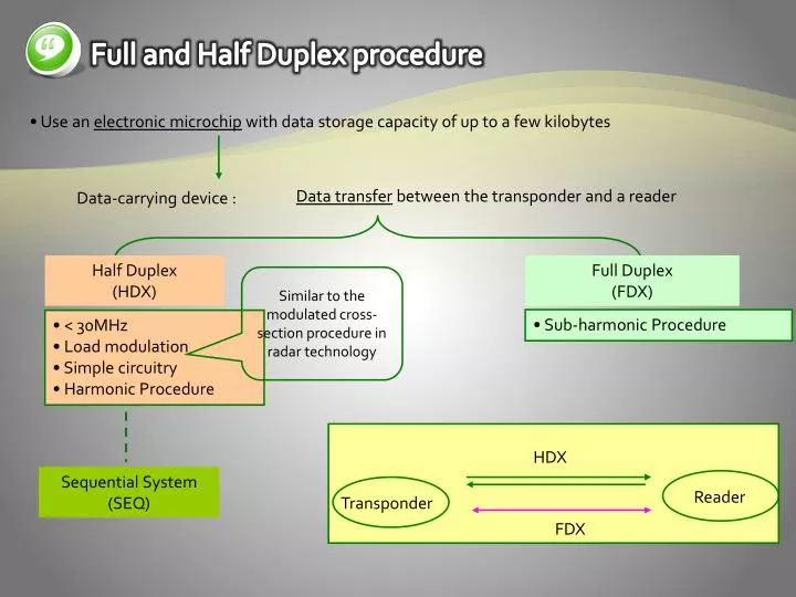
Full and Half Duplex procedure. Use an electronic microchip with data storage capacity of up to a few kilobytes. Data transfer between the transponder and a reader. Data-carrying device :. Half Duplex (HDX). Full Duplex (FDX).

E N D
Full and Half Duplex procedure • Use an electronic microchip with data storage capacity of up to a few kilobytes Data transfer between the transponder and a reader Data-carrying device : Half Duplex (HDX) Full Duplex (FDX) Similar to the modulated cross-section procedure in radar technology • Sub-harmonic Procedure • < 30MHz • Load modulation • Simple circuitry • Harmonic Procedure HDX Sequential System (SEQ) Reader Transponder FDX
Full and Half Duplex procedure • Down link : data transfer from the reader to the transponder
Inductive Coupling Power supply to passive transponders weak transformer-type coupling DC Power Generation Magnetic field H Rectification Reader Transponder Resonance Capacitor Resonance Capacitor trimming cap. to compensate for resonance frequency manufacturing tolerances Typical 100-1000 windings 135 kHz Typical 3-10 windings 13.56MHz
Inductive Coupling Different designs of inductively coupled transponders. The photo shows half finished transponders, i.e. transponders before injection into a plastic housing (reproduced by permission of AmaTech GmbH & Co. KG, D-Pfronten)
Inductive Coupling Reader for inductively coupled transponder in the frequency range <135 kHz with integral antenna (reproduced by permission of easy-key System, micron, Halbergmoos)
: transponderreader Data Transfer Transponder Magnetic field H Binary Code Signal, subcarrier freq. (fs) Load modulation Modulation product by load modulation with subcarrier signal Generation of load modulation in the transponder by switching the drain-source resistance of an FET on the chip.
13.56MHz Q : TP 가 Reader기로 너무 가까이 가면 ? Subcarrier (212 kHz) /64 Divider Full-wave Rectifier NAND SW w.r.t output of IC3a Data Transfer Example : circuit-load modulation withsubcarrier
128 kHz 64 kHz 128 kHz Subcarrier (64 kHz) Inductive Coupling Example : Subharmonic Procedure Basic circuit of a transponder with subharmonic back frequency
Electromagnetic Backscatter Coupling Q : RFID의 인식거리를 넓히고자 한다. 사용 주파수와 인식거리와의 관계는 ? RFID systems in which the gap between reader and transponder is greater than 1m Long-range systems UHF frequencies : 868 MHz (Europe), 915MHz (USA) 908.5~914MHz (Korea) Short Wavelength Microwave frequencies : 2.5GHz, 5.8GHz ANT size & Efficiency Free space path loss Free space path loss aF at different frequencies and distances. the transponder’s antenna gain : 1.64 (dipole), the reader’s antenna gain : 1 (isotropic)
Active Transponder antenna Lithium batteries Active transponder for the frequency range 2.45 GHz.
Data Transmission The efficiency with which an object reflects electromagnetic waves. reflection cross-section Operating principle of a backscatter transponder. The impedance of the chip is ‘modulated’ by switching the chip’s FET
2 Full and Half Duplex Procedure Close Coupling Close coupling systems ranges between 0.1 cm and a maximum of 1 cm. • frequency range : 1-10MHz • Efficiency : Very good Close coupling transponder in an insertion reader with magnetic coupling coils The mechanical and electrical parameters of contactless close coupling chip cards standard, ISO 10536
: transponderreader Data Transfer Magnetic Coupling Load Modulation in close coupling systems Plate capacitors are constructed from coupling surfaces isolated from one another. Capacitive Coupling Reader’s coupling surface Electrical Field E Transponder’s coupling surface Capacitive coupling in close coupling systems
Electrical Coupling Capacitive coupling 1m의 거리에서 전극 크기 a×b=4.5cm×7cm (스마트 카드에 대응하는 형태)를 갖는 트랜스폰더 읽기를 위해 필요한 전극 전압(f=125kHz) An electrically coupled system
2 Full and Half Duplex Procedure : transponderreader Data Transfer Equivalent circuit diagram of an electrically coupled RFID system 3.2.5 Data Transfer : Reader Transponder Because of the simplicity of demodulation, the majority of systems use ASK modulation. • ASK: amplitude shift keying • FSK: frequency shift keying • PSK: phase shift keying