Download
1 / 48
480 likes | 481 Views
US LHC Accelerator Research Program. BNL - FNAL- LBNL - SLAC. LARP Accelerator Systems. 16 November 2011 LARP CM17/HL-LHC at CERN Tom Markiewicz/SLAC. The LARP Accelerator Systems Program. “Instrumentation” Completed Schottky Monitor, Tune & Chromaticity FB, AC Dipole

E N D
US LHC Accelerator Research Program BNL - FNAL- LBNL - SLAC LARP Accelerator Systems 16 November 2011 LARP CM17/HL-LHC at CERN Tom Markiewicz/SLAC
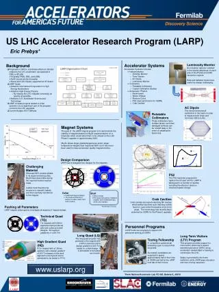
The LARP Accelerator Systems Program • “Instrumentation” • Completed Schottky Monitor, Tune & Chromaticity FB, AC Dipole • Ongoing Commissioning Support for the Lumi Monitor • Support for modest LLRF and SLM collaboration • “Collimation” • Phase II Collimator “Rotatable Collimator” Prototype • Crystal Collimation at Tevatron (T980) and SPS (UA9) • “Accelerator Physics” • Simulation-dominated effort in Beam-Beam → Hollow Electron Beam Gun for use as a Collimation Scraper • Simulation-dominated study of Ecloud effects → High Bandwidth Feedback Control of Ecloud/TCMI in SPS • Crab cavity: Cavity Design and related Beam Physics • Hi-Lumi Accelerator Physics in support of Magnet Program • Completed PS2 Study & Hibernated PSB Study Accelerator Systems - T. Markiewicz
Schedule for Accelerator Systems Parallel Session This Afternoon Accelerator Systems - T. Markiewicz
In 2012 SPS Ecloud FB & Crab Cavity Are Largest LARP AS Budget Items * SUBSTANTIAL un-billed Labor from, especially, Fermilab NOT included Accelerator Systems - T. Markiewicz
Pre-CC’11 Comments on the LARP CRAB CAVITY Program • Highlights of December 2010 CC’10 meeting at CERN • Design capable of crossing beams in either H or V preferable • No test of KEK-B Cavity in SPS • New SLAC Design to Satisfy H-V specification • “Compact Ridged Waveguide Deflector” • Tweaking of ODU/JLAB Parallel bar Design for H & V Crabbing • “Rigid Waveguide” and “Parallel Bar” designs beginning to look similar and agreement to merge designs made • SLAC offer to analyze all designs under consideration with Advanced Computing Division tool suite met with approval • Rama Calaga no longer LARP funded (Congratulations!!) • LARP Crab “Leadership” & Role of BNL under discussion • New full time postdoc for Old Dominion (plus previous student support) • Increased support for SLAC ACD • Still no consensus for how to “projectize” effort (& get engineering funds) Accelerator Systems - T. Markiewicz
MultiPactering Analysis of SLAC Compact 1-D Half Wave Spoke Resonator Cavity Impressive Visualization of Resonant MP Z. Li Accelerator Systems - T. Markiewicz LOM/HOM-v HOM-h FPC
SLAC Ridged Waveguide Deflector for H & V Crabbing Z. Li Accelerator Systems - T. Markiewicz
Current ODU Crab Cavity Design Program ODU/Niowave Phase II STTR Current Design J. Delayen Accelerator Systems - T. Markiewicz
Example of Multipacting Simulation Using Track3Pon ODU Prototype Cavity Z. Li Accelerator Systems - T. Markiewicz
Transverse Wideband Feedback for Ecloud/TMCI in the SPSTask Leader: John Fox • SLAC Accelerator Research Department: • J. Cesaratto (newest LARP Toohig Fellow, November 2011) • J. D. Fox, M. Pivi, C. Rivetta • O. Turgut, S. Uemura (graduate students) • BE-RF Group, CERN: • G. Arduini, W. Hofle, K. Li, G. Rumolo, B. Salvant • LBL: • M. Furman, M. Venturini, S. De Santis, J.-L. Vay • R. Secondo (graduate student) Accelerator Systems - T. Markiewicz
2011 Ecloud/TMCI Progress • A vertical excitation system was developed, tested, and installed in the SPS • Existing pickups for driving bunch & measuring response • Four 100W 20-1000 MHz amplifier array • 4 Gsample/sec D/A synched to RF and software tools to drive individual bunches • Data collected during the July/August and November 2011 Machine Development runs at the SPS used to understand Ecloud/TMCI dynamics and to develop reduced models and numeric simulations • Modeling in WAP, CMAD and Head-Tail Codes • Extraction of system dynamics • Develop a simplified coupled-oscillator model for feedback design Accelerator Systems - T. Markiewicz
Broadband 100W 20 - 1000 Mhz amplifiers under construction & test Sho Uemura Accelerator Systems - T. Markiewicz
4 GigaSample/s D/A Synched to RF and software tools to drive individual bunches Accelerator Systems - T. Markiewicz
Amplifiers Shipped, Installed & Connected to SPS Kicker Accelerator Systems - T. Markiewicz
Results from Excitation studies • A single bunch of stable beam is excited by the amplifier array • The excitation system drives the bunch at mode 0, mode 1, etc. frequencies • Bunch motion is studied via pickup array and receiver system, digitized at 40 GS/sec. • Barycentric, head-tail or higher modes are excited • Study dynamics as currents are increased towards instability thresholds • Movies ( time domain), and Spectrograms ( frequency domain) Accelerator Systems - T. Markiewicz
Modeling • Extraction of system dynamics • Development of reduced (linear) coupled-oscillator model for feedback design • Inclusion of feedback models in WARP, CMAD and Head-Tail codes C-MAD result: Vertical displacement of center of the bunch Data: Vertical displacement of center of the bunch Kicker signal for all the slices: Vb = 4E-6sin(2π(0.185Turns)) eV-sec/m Accelerator Systems - T. Markiewicz
2012 Ecloud/TMCI Plan • Develop 4 GS/sec. proof of principle feedback system • Identify critical technology options, evaluate difficulty of technical implementation • Explore ’small prototype’ functional feedback channel for 2012 fab and MD use • Evaluation boards being used to explore feedback parameters • R. Secondo (LBL) is now working on a equalizer design to process the pickup signals: • part of the proof-of-principle system in development for tests at the SPS • Both a prototype and full scale feedback system are beyond scope of LARP’s budget • SPS Kicker Design Study: develop wideband prototype • Goal is prototype kicker & feedback installation in SPS in 2013-14 shutdown Accelerator Systems - T. Markiewicz
Loss Maps & Energy Deposition Studies in Support of Nb3Sn Magnet Design • Funding began summer 2011 with FY11 contingency request and continued in FY12 at same level • In line with DOE reviewer comments for AP support of LARP magnet design • In line with HL-LHC Accelerator Physics task (Hi Lumi WP2) • General agreement by all AP parties that this is good • Led by Nikolai Mokhov/Fermilab with MARS-based tools • Led by Yunhai Cai/SLAC with suite of agreed upon AP codes • Communication with CERN (Bruning et al) and Magnet side required for success • This has begun within the context of Hi-Lum Work Package 2 • Subtask Leader: M. Giovannozzi Accelerator Systems - T. Markiewicz
LHC Beam Dynamics and Collimation Studies at SLAC • SLAC members involved • Yunhai Cai, Yi Jiao, Yuri Nosochkov, Lanfa Wang, Min-Huey Wang, Yiton Yan • CERN members in contact and for discussion • M. Giovannozzi , R. Assmann, Y. Levinsen, E. Mcintosh, A. Rossi, F. Schmidt • Lattice: ATS collision scheme “4444” with b*=15/15 cm at IP1 and IP5 • Codes: SixTrack, MAD-X. • Proposed topics of studies • Field quality specifications for the new triplet quadrupoles . • Computation of collimation loss maps. • High order map analysis. • Chromatic effects on beam cleaning efficiency. • Chromatic aberrations for the collimation system. • 6-D beam-beam effects.
Status and Highlight • Current studies: • Numerous dynamic aperture studies are carried out to declare the “first round” triplet tolerance error table based on global scaling of the field coefficients. • Preliminary calculation of the beam loss map is done for the ATS collision lattice “4444”. • Further studies: • Analysis of sources for dynamic aperture reduction (effects of arc beta beat and non-paired sextupoles). • The “Second round” triplet tolerance error table is to be based on relaxing field error coefficients one-by-one -- more realistic for the magnet design. • more detailed calculation of collimation beam loss map. • Future studies: Analyses of High-order maps, chromatic effects, and 6-D Beam-beam effects for the ATS lattice. • Highlight: “First round” tolerance table in the next slide.
ATS “4444 First Round” IT Tolerance Error Table (Rref = 50 mm)
15mm Hollow Electron Gun Accelerator Systems - T. Markiewicz
Hollow Electron Beam Gun in Tevatron • 18 experiments 2010.10-2011.06 • Tail of selected bunch depopulated • Control bunches & core of selected bunch unaffected Accelerator Systems - T. Markiewicz
Sample HEBC Results: Selected & Control Bunch Intensity vs. Beam Size • Excellent progress in understanding of hollow beam collimation • Many new observations: halo removal rates, effects on core, • diffusion, fluctuations in losses, collimation efficiencies, ... Accelerator Systems - T. Markiewicz
Sample HEBC Results: Signal on Gated Loss Monitor for Selected & Control Bunch Accelerator Systems - T. Markiewicz
New 25mm Hollow Gun for Stronger Scraping • 25 mm diameter cathode vs. 15 mm previously • 3A at 5 kV vs. 1A • Technical feasibility study • Currently assembled, • installed at test stand • Bakeout, cathode heating Accelerator Systems - T. Markiewicz
Discussions of Bringing Electron Lens Hardware to CERN Underway Accelerator Systems - T. Markiewicz
Luminosity Monitor Commissioning Status A.Ratti, H. Mathis, M. Stezelberger, M. Placidi LBNL
Lumi Status • All four devices (two per IP) have been functioning very reliably since the beginning • As single bunch luminosity increases, we are moving from counting mode (saturating) to pulse height mode (not effective at lower lumi) • FLUKA modeling continues to provide useful support
Lumi Update since the June DOE review Modeling • Completed integration of the FLUKA model of the IPs (from CERN) with the detailed LBL model of the TAN and BRAN • Summer Student (D. Nguyen – UT Austin) • Completed transition to FLUKA 2011 • Improved results of crossing angle calculations at 3.5, 5 and 7 TeV per beam
Energy Deposition per p-p collisionvs crossing angle (from FLUKA) Ecross = (E1 + E4) – (E2 +E3) E1 + E2 + E3 + E4
Operational Experience • Continued to develop operator user interface for use in the CCC • All software effort thanks to Elliott McCrory (FNAL) • Coordinated at CERN by Terri Lahey (SLAC) • This GUI is starting to be used in CCC • See example next • Becoming a tool for beam physics measurements. Can show: • Beam beam effects • Emittance growth
GUI diagnostics example • Example from Aug. 6 (fill 2007) • Emittance blowup of one batch during injection • Disappointing early luminosity • GUI was used to identify which batch immediately
New GUI for use in the CCC System Parameters Emittance Atlas and CMS Luminosity Atlas and CMS B by B lumi @ ATLAS B by B lumi @ CMS Bad Batch B by B Emitt.@ CMS B by B Emitt.@ ATLAS
Synchrotron Light Based Halo Monitoring • LARP involved with SLM (Alan Fisher, SLAC) and Collimation • SLAC interest (SSRL) independent of LHC-tested October 2011 • Use a “Digital Micro Mirror Device” (DMD) as an ADJUSTABLE MASK to black out light from beam core so can see halo • Suggested by Karsten Welch, EU funded DITANET: students may be available Accelerator Systems - T. Markiewicz
DMD Masking Experiments at SPEAR3 Oct-Nov 2011 Ralph Fiorito, A.Shkvarunets, H.Zhang –University of Maryland J.Corbett, A.Fisher, K.Tian – SLAC T.Mitsuhashi (KEK, Japan), W.Mok (Visiting scientist), J.Kamp (Summer student) Oscillating injected beam (~30pC) Intense stored beam (few nC) Airforce Target Calibration Incident beam DMD 5x Magnification Gated Camera w/intensifier J. Corbett Turn #6 Turn #3 Turn #4 Turn #5 Turn #2 Turn #1 mask diffraction injected beam
Measuring the Size of Every Bunch Every Second • Slowly rotating wheel (0.25 Hz) scans 3 thin slots across the image of the beam • PMT after slot gives pulse for each bunch • As slot passes by, digitize 100 pulses for each bunch • Projects each bunch onto x, y, and 45° axes Y slot 45° slot X slot Beam A. Fisher X profile of a bunch in SPEAR3 15-µm wide slot in foil Al discs to support foil Accelerator Systems - T. Markiewicz
LHC LLRF and Longitudinal Beam Dynamics Purpose: LHC non-linear beam dynamics-RF station simulation and system model. • The model captures engineering level implementation details. People: • SLAC: J.D.Fox, C. Rivetta, D. Van Winkle • CERN: P. Baudrenghien, A. Butterworth, T. Mastorides, J. Molendijk Results in 2009-2010: • The LLRF configuration tools have been used by the CERN BE-RF group to remotely commission the LLRF feedback loops of the RF stations during start up in both November 2009 / February 2010. • Tools reduced commissioning from 1.5 days/station to 1.5 hours/station. • Model based configuration adds consistency and reliability. • CERN BE-RF group have repeatedly expressed their support and proposes • Continue work to test the 1-turn feedback functionality of the commissioning tools • Expansion of the tools to control the smooth increase of the High Voltage and Klystron current with beam, from 450 GeV conditions to ramping/physics
Beam Diffusion Studies and LLRF System Noise Contributions • RF Noise Effect on Beam Diffusion Studies • Developed theoretical formalism relating the equilibrium bunch length with beam dynamics, accelerating voltage noise, and RF system configurations. • Conducted measurements that • confirmed the formalism and models • identified performance-limiting components • RF reference noise introduced by controller in mod/demodulation process • Intrinsic noise in the controller feedback boards • set an allowable noise threshold for acceptable lifetime. • Predictions of beam longitudinal motion and RF station stability limits for future high current/higher energy LHC operations • Estimate longitudinal stability margin for 2012 operations. • Impact of future LLRF configurations on RF noise levels is being investigated.
The LARP Rotatable Collimator PrototypeCandidate for a Phase II Secondary Collimator • Two jaw collimator made of Glidcop • Rotate jaw after 1MJoule beam abort failure accident occurs • Each jaw is a cylinder with an embedded brazed cooling coil • No vacuum-water braze; 12kW/jaw cooling; minimal thermal distortion • Maximum radius cylinder possible given beam pipe separation • 20 2cm wide facets provided for presumed rare beam abort accidents • Advantages: • Not exotic material • High Z for better collimation efficiency & more debris absorption • Low resistance for better impedance • Elemental for high radiation resistance • Disadvantages: • Glidcop WILL be damaged in asynchronous beam abort Accelerator Systems - T. Markiewicz
Collimator Assembled 13-Mar-11Mechanical & Resistance Tests Good Accelerator Systems - T. Markiewicz
Vacuum Tests • After welding tank to base and copper cooling tubes to feedthroughs at bottom of bellows discover major “water-to-vacuum” leak in each cooling tube • Each tube was tested at various stages in fabrication process but not at every stage of fabrication and not at final stage • Since then • Cap the tubes and: • Test rotation mechanism under vacuum – Good • 5 week vacuum bakeout, pressure test and RGA scan- few x E-9 torr • Test rotation mechanism after bakeout – • One gear jammed; repaired easily; cause understood • Cut open the tank, cut out the jaws & find leaks • Jaw A has crack in tube wall in stress free area: repaired • Jaw B leak isolated to small zone at rear of collimator • Jaw material being cut now to expose tube for repair • Discussions with CERN, SLAC, LARP & DOE as to best course of action Accelerator Systems - T. Markiewicz
When Cooling Tubes Capped and Tank Pumped Vacuum IS Good Pressure: 1.9E-5 Torr (Cold Cathode Gauge on tank) Leak rate: 5.9E-10 mbar-l/sec (on the Adixen input) Pressure rate of rise Leak rate of ~1E-4 torr/hour Accelerator Systems - T. Markiewicz
Final RGA after 5 week 250˚C bakeout(Blue bar is ideal level), P=4.4E-9 torr Accelerator Systems - T. Markiewicz
Crack in Copper Magnet Conductor Used for Winding First Prototype Jaw • Tube is not Class 1 OFE • was thought to be OK for a prototype to get started • Suspect weakening in material at crystal grain boundaries after last of many high temperature firings Accelerator Systems - T. Markiewicz
Leak in OFE Class 1 Copper Tubing Isolated to Area Indicated Suspect damage at tack welds used during assembly Accelerator Systems - T. Markiewicz
Summary • Major shift in emphasis away from Luminosity Monitor and Rotatable Collimator to the SPS Wideband FB Control of Ecloud/TCMI and the Crab Cavity • New effort in Accelerator Physics in support of HL-LHC and the LARP magnet program • Superb new experimental results from the Hollow Beam Electron Gun and interest in bringing it to CERN • Continued excellent work in the Luminosity Monitor, LLRF, SLM, as well as the Crystal Collimation experiments & Schottky monitor (apology) • Continuing effort to recover the Rotatable Collimator Phase II Prototype program. Accelerator Systems - T. Markiewicz