Download
1 / 43
560 likes | 977 Views
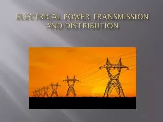
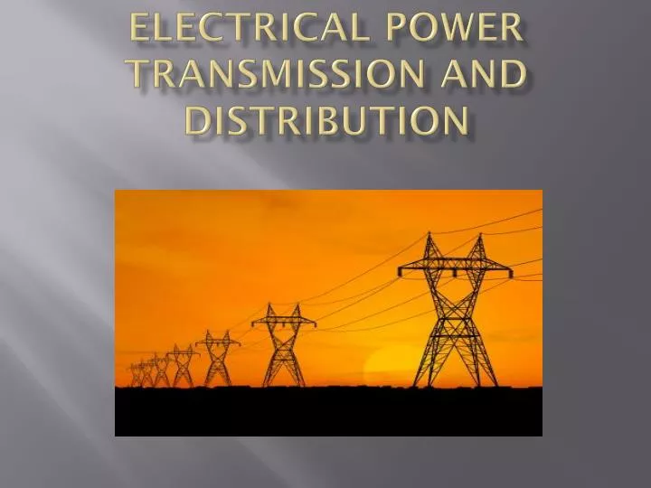
Electrical Power Transmission and Distribution. Single Phase Transformer. A transformer is an electrical device that is used to raise or lower the voltage (or current) level. A single-phase transformer has two electrically isolated windings.

E N D
Single Phase Transformer • A transformer is an electrical device that is used to raise or lower the voltage (or current) level. • A single-phase transformer has two electrically isolated windings. • The winding that is connected to the electrical power source is called the “primary” winding. • The winding that is used to draw electrical power is called the “secondary” winding. ENS 441/ELT 437
Ideal Transformer Figure below shows a schematic diagram of an ideal single-phase transformer. EP = induced voltage on the primary side (RMS) ES = induced voltage on the secondary side (RMS) NP = Number of turns on the primary windings NS = Number of turns on the secondary windings Φm = magnetic flux created by the source voltage E Φm ENS 441/ELT 437
Ideal Transformer • When the primary winding is connected to an AC power source it produces an instantaneous magnetic flux “Φm(t)” linking the primary as well as secondary windings of the transformer. • The flux linkage induces an instantaneous voltage “Ep(t)” in the primary winding in accordance with the Faraday’s law of electromagnetic induction. That is, ENS 441/ELT 437
Ideal Transformer Since the voltage applied at the primary is sinusoidal, therefore, the magnetic flux Φm(t) is also sinusoidal and mathematically it can be expressed as . Therefore, or ENS 441/ELT 437
Ideal Transformer Substituting and we get Above Eq. shows that the induced voltage Ep(t) leads the magnetic flux Φm(t) by 90o. The RMS value of Ep(t), denoted by Ep is given by or (1) ENS 441/ELT 437
Ideal Transformer Since the magnetic flux Φm(t) also links the secondary winding that has Ns turns, the RMS value of the induced voltage at the secondary side of the transformer, denoted by Es is given by (2) Comparing Eqs. (1) and (2) yields or ENS 441/ELT 437
Ideal Transformer or or where, “a” is called the turn ratio of the transformer. ENS 441/ELT 437
Single Phase Transformer Figure below shows an ideal transformer with a load on the secondary side. ENS 441/ELT 437
Ideal Transformer • Under ideal conditions no current flows through the primary winding and the primary current “IP” is zero when secondary side is open. • When a load is connected to the secondary side, a current, Is, flows out of the secondary windings. • The secondary current, Is, creates a magnetic flux “Φs” in the transformer’s core. • Since the source voltage, E, is unchanged, which mean the flux, Φm, must remain the same as it was before the load was connected. • Therefore, the new flux (Φs) due to the secondary the current, Is, must be countered by an equal and opposite flux. ENS 441/ELT 437
Ideal Transformer • The counter flux “Φp” is produced by causing a current, Ip, to flow into the primary windings. • Under ideal conditions, the fluxes Φsand Φp cancel each other and the total flux through the core remains Φm. • Result: Primary and secondary induced voltages (Ep and Es) remain unchanged. • The flow of the primary current, Ip, represents the power transfer from primary side to the secondary side of the transformer to support the load Zs. • Under ideal conditions there is no loss of power during the power transfer from the primary side to the secondary side of the transformer. ENS 441/ELT 437
Ideal Transformer Therefore, the total power, Sp, on the primary side of the transformer must be equal to the total power, Ss, on the secondary side of the transformer, where and but Sp= Ss, therefore, But , therefore, or ENS 441/ELT 437
Ideal Transformer The load impedance as seen by the primary side, denoted by Zp, can be given by but . Therefore, Above Eq. shows an important property of the transformer; that is, it can be used to change the effective impedance of any load and thus can also act as an impedance transformer. ENS 441/ELT 437
Ideal Transformer Using impedance transformation, the impedances on the secondary side can be expressed as the equivalent impedances on the primary side to greatly simplify the circuit analysis involving transformers. ENS 441/ELT 437
Practical Transformer • The ideal transformer is lossless. • In a real transformer, however, the primary current is not zero under no-load condition. • Reason: Iron losses and magnetizing reactance • Causes of iron loss: • Eddy currents • Hysteresis losses ENS 441/ELT 437
Practical Transformer Eddy Current Losses: • When time-varying magnetic flux passes through a solid metallic core, the solid metallic core acts like a bundle of concentric conductors and a voltage is induced in each of these sections of the metallic core. • In a solid metal plate each of these sections would behave like a short-circuited conductor and, therefore, the induce voltages would cause a strong currents which swirl back and forth in the core. • These currents are called eddy currents. ENS 441/ELT 437
Practical Transformer Eddy currents are a major source of generating heat in transformers. In a solid metal core these currents can be so strong that they render the core red hot. • Solution: Design the core with thin laminated strips to insulates the strips from each other. • Result: The length of the conducting path is greatly reduced. • Magnitudes of the induced voltages in the core thereby diminishing eddy current losses. ENS 441/ELT 437
Practical Transformer Hysteresis Losses The magnetic flux is caused by magnetic field strength, H. The resulting flux density, B, in any material is related to the magnetic field strength (H) by the following equation: where, B = magnetic flux density (weber/m2 or tesla) H = magnetic field strength (A-turns/m) µo = permeability of free space = µr = relative permeability of the material The value of µr changes with flux and, therefore, the relationship between B and H is expressed in terms of a B-H curve. ENS 441/ELT 437
Practical Transformer Figure below shows the closed B-H curve called hysteresis loop. • The area under this curve represents the energy that changes into heat during each cycle (joules per cubic meters). • Iron losses are represented as resistance (Rm) in parallel to the primary terminals of the transformer. ENS 441/ELT 437
Practical Transformer • Magnetizing Inductance: In order to generate the magnetic flux Φm, a current must flow through the primary windings. • This current is called magnetizing current and depends on the permeability of the material used to build the core. • Higher permeability means lower magnetic current and vice versa. • Permeability can be represented by a parallel inductance (Xm) to the primary terminal because magnetizing current does not affect the amount of induced voltage. • This inductance is called magnetizing inductance. ENS 441/ELT 437
Practical Transformer Winding Resistance: • In a real transformer, the winding of the transformer have finite resistance that must be taken into account while analyzing or modeling a practical transformer. • Since these winding resistances result in a potential drop when current passes through the windings, they are represented as the series resistors (Rpand RS), both at the primary as well as at the secondary side of the transformer. ENS 441/ELT 437
Practical Transformer Leakage Flux: • In a real transformer some of Φs and Φp does leak in the air. • This flux leakage induces voltages both in the primary winding and secondary windings, which is counter to the voltages induced by the flux Φm. • It results in a voltage drop both at the primary as well as the secondary side. • Accordingly, the effect of the leakage flux is represented as the series impedances (Xlpand Xls) at the primary as well as the secondary side of the transformer in the model of a practical transformer. ENS 441/ELT 437
Practical Transformer Figure below shows the complete model of practical transformer that incorporate the iron losses, magnetizing current, primary and secondary winding resistances, and the effect of the leakage flux under load conditions. ENS 441/ELT 437
Practical Transformer The model of the practical transformer is easier to analyze if the elements on the secondary side are shifted to the primary side as shown in Fig. below. ENS 441/ELT 437
Practical Transformer No-load Condition: Under no-load condition the secondary is open and, therefore, no current flows through the secondary terminals. ENS 441/ELT 437
Practical Transformer Full-load Condition: Under the full-load condition and, therefore, we can ignore Rm and Xm and the model for the practical transformer reduces to the one shown below. ENS 441/ELT 437
Practical Transformer The model of the practical transformer can further be simplified by adding the resistances and inductances as follows: and Furthermore, Rlp and Xlp can be represented by the complex impedance Zpas follow: ENS 441/ELT 437
Practical Transformer Figure below shows the simplified circuit for the practical transformer with full load. ENS 441/ELT 437
Practical Transformer Example: Specifications of a power transformer are as follows: Compute the full-load Vs, Is, as well as heat dissipation in the transformer using the simplified model. Also, compute Iron losses using the model under no-load condition . ENS 441/ELT 437
Practical Transformer Solution: Let’s assume it’s a pure resistive load and full-load secondary voltage is the same as Vns and full-load secondary current is the same as Ins. Now we can calculate the load resistance, RL, as follows: The turn ratio is given by Now we can compute Rep and Xep ENS 441/ELT 437
Practical Transformer The resistance shifted to primary, RLp, is given by Now we can compute the total impedance of the model, ZTp, as follows Now we can compute primary current, Ip, primary voltage, Ep, secondary current, Is, and secondary voltage, Es as follows ENS 441/ELT 437
Practical Transformer Now we can compute the heat loss due to the load as follows Finally, we’ll compute iron losses at no load and at full load as follows ENS 441/ELT 437
Practical Transformer Total power loss at full load = 10.69 + 10.74 = 21.43 KW. This power loss produces significant amount of heat that must be removed from the transformer to avoid any damage to transformer. ENS 441/ELT 437
Practical Transformer • There are a number of techniques that are used in the transformers to remove heat. • Through natural circulation of air (type AA), • Through forced air circulation (type AFA), • Oil-immersed self-cooled (OA), • Oil immersed self-cooled/forced air cooled (type OA/FA) to name a few. ENS 441/ELT 437
Practical Transformer Figure below show the front view of an OA/FA type power transformer. ENS 441/ELT 437
Practical Transformer • Figure next shows the rear view of the same transformer where cooling fans can be seen which remove heat from the transformer through forced air circulation. • A transformer is called a “step-down” transformer if the secondary voltage, ES, is lower than the primary voltage, EP. On the hand, if the secondary voltage is higher than the primary voltage, it is called a “step-up” transformer. ENS 441/ELT 437
Practical Transformer Terminal Marking on Power Transformers: • In power transformers, the high voltage (HV) terminals are marked by symbols H1 and H2. • The low voltage (LV) terminal are marked by symbols X1 and X2. • These terminals are mounted on the transformer tank in a way that they either have additive polarity or they have subtractive polarity. ENS 441/ELT 437
Practical Transformer Figure below shows the terminal marking and polarity of the power transformers. • It is imperative to know the correct polarity of the transformers if you are connecting them in parallel or configuring a 3-phase transformer bank using single phase transformers. ENS 441/ELT 437
Practical Transformer • Voltage Regulation: • Voltage regulation is measure of variation in the secondary voltage from no-load to full-load condition when the primary voltage is kept constant. • Voltage regulation is expressed in percent (%) and is defined by the following equation ENS 441/ELT 437
Power in AC Systems In AC systems the power is divided into three different categories: Apparent Power: • It is the product of the voltage and complex conjugate of the current and is expressed in “volt-amperes” or VA. • If the current I = IR + j IX then the conjugate of I, denoted by I*, is given by I*= IR – j IX. The apparent power, PA, is given by ENS 441/ELT 437
Power in AC Systems Real Power: • The real power (PR) is the power utilized by a user and is expressed in watts (W). • When the apparent power is expressed in rectangular form, the real part of the apparent power is the real power. • The real power always flows from the source to the user. ENS 441/ELT 437
Power in AC Systems Reactive Power: • The reactive power (PX)is needed to establish magnetic field in inductors. • Electric field in a capacitor acts as a source of reactive power. • Reactive power can be supplied as well as absorbed by an electric power source. It means that the reactive power can flow from the source to the circuit or from the circuit to the source. ENS 441/ELT 437
Power in AC Systems • When the reactive power flows from the source to the circuit it is considered “positive” reactive power. • However, it is considered “negative” reactive power when it flows from the circuit to the source. • Mathematically, the apparent power(PA), the real power (PR), and the reactive power (PX) are related as follow: ENS 441/ELT 437