Download
1 / 14
140 likes | 243 Views
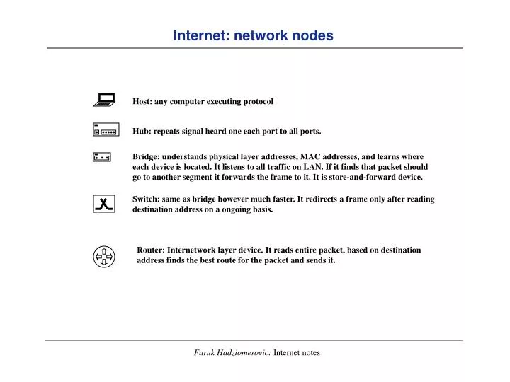
Internet: network nodes. Host: any computer executing protocol. Hub: repeats signal heard one each port to all ports. Bridge: understands physical layer addresses, MAC addresses, and learns where each device is located. It listens to all traffic on LAN. If it finds that packet should

E N D
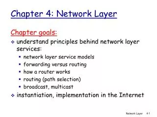
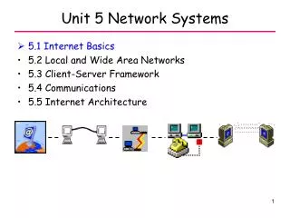
Internet: network nodes Host: any computer executing protocol Hub: repeats signal heard one each port to all ports. Bridge: understands physical layer addresses, MAC addresses, and learns where each device is located. It listens to all traffic on LAN. If it finds that packet should go to another segment it forwards the frame to it. It is store-and-forward device. Switch: same as bridge however much faster. It redirects a frame only after reading destination address on a ongoing basis. Router: Internetwork layer device. It reads entire packet, based on destination address finds the best route for the packet and sends it.
Internet: network of networks star star hub bridge hub token ring switch bridge bridge Ethernet Ethernet router
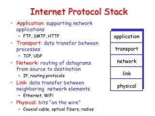
Application Layer Presentation Layer Session Layer Transport Layer Network Layer Data Link Layer Physical Layer Internet protocol stack vs. OSI model (Fig. 1.2) Process Layer E-mail, FTP, HTTP Host-to-host Layer TCP, UDP Internet Layer IP, ARP MAC* Layer Ethernet, Token ring (ATM, Frame Relay**) Physical Layer Manchester * Medium Access Control. MAC and Physical layers are called Network Interface Layer. ** not exactly MAC, however, layer above physical
FTP client FTP server TCP TCP IP IP IP Token ring driver Token ring driver Ethernet driver Ethernet driver Two networks connected with a router (Fig. 1.3) Token ring host Ethernet host FTP protocol TCP protocol router IP protocol IP protocol Ethernet protocol Ethernet protocol Ethernet Token ring
IGRP 88 ICMP 01 Ethernet, Token Ring, FDDI, SLIP, PPP, etc. Internet protocol suite Telnet BOOTP HTTP DHCP TFTP SNMP FTP DNS RIP Process Layer Port Numbers 23 20/21 80 53 67/68 69 151/162 520 Host to Host Layer TCP UDP 6 17 OSPF Protocol Codes 89 Internet Layer ARP IP RARP 0806 0800 0806 Network Interface Layer
Internet protocols TELNET - remote terminal connection service. Allows user terminal to mimic the terminal at the remote side. FTP - File Transfer Protocol (put/get file to/from remote machine). HTTP - Hypertext Transport Protocol. DNS - Domain Name Server On-line distributed database for translating IP machine names into IP addresses. BOOTP - Bootstrap Protocol defines each device autoconfiguration on the server (improvement to the RARP). DHCP - Dynamic Host Configuration Protocol (improvement to BOOTP) allows network administrator to configure workstation by providing dynamic address assignment. TFTP - Trivial File Transfer Protocol (same as FTP with minimal capability). SNMP - Simple Network Monitoring Protocol used to monitor IP gateways and networks they are attached to. RIP - Routing Information Protocol used to exchange the routing information among small set of computers (every 30 sec hosts exchange information). TCP - reliable Transmission Control Protocol (connection oriented). UDP - unreliable Universal Transport Protocol (connectionless). IGRP - Interior Gateway Routing Protocol (proprietary routing protocol developed by Cisco). ICMP - Internet Control Message Protocol part of IP that handles error and control messages. OSPF - Open Shortest Path First routing protocol. ARP - Address Resolution Protocol used to dynamically bind IP addresses to physical addresses. RARP - Reverse ARP used by newly installed machine to find its IP address. IP - Internet Protocol.
Application UDP 8 bytes variable Ethernet IP header Application CRC TCP 14 bytes 20 or 24 variable 20 to 60 bytes Encapsulation (Fig. 1.7) 4 bytes ICMP 6 + bytes
application application application application TCP UDP ICMP IP Ethernet driver IGMP RARP ARP incoming frame Demultiplexing (Fig. 1.8)
aix .1.92 .1.183 Telebit NetBlazer netb modem Sample (book) network Solaris 2.2 SunOS 4.1.1 Cisco router gateway solaris gemini .1.32 .1.11 .1.4 Ethernet All IP addresses belong to class B network ID 140.252.xxx.xxx SLIP (dialup) modem BSD/386 1.0 BSD/386 1.0 SVR4 SunOS 4.1.3 .1.29 slip bsdi svr4 sun .13.66 .13.65 .13.35 .13.33 .13.34 Ethernet
Link Layer (Fig. 2.1) SLIP (Serial Line IP) c0 db ESC dc dd c0 db db c0 Point-to-point (PPP) protocol addr FF Flag 7E Contr 03 Flag 7E protocol data CRC 1 1 1 2 up to 1500 2 1 0021 IP datagram C021 Link control data 8021 network control data
Ethernet Header Destin. Addr. Type Source Addr. ff ff ff ff ff ff 00 00 c0 a0 51 24 08 06 ARP Unicast Broadcast 01 00 5e 00 00 00 00 00 c0 a0 51 24 08 00 IP Unicast Multicast 01 00 c0 a0 51 24 00 c0 93 21 88 a7 81 4c SNMP Unicast Unicast Vendor addr component Vendor ser. number
IP addressing convention 4 bytes (dec): 140.252.1.13 = 01100000.10101010.00000001.00001011 Class A: Large networks (GM, Ford, etc) N-Network bits L-Locally administered 126 Class A networks 16,777,214 hosts/network 0NNNNNNN LLLLLLLL LLLLLLLL LLLLLLLL 0 - unused, 1 .. 126 ; 127 - loop back Class B: medium size (universities, medium business) 16,384 Class B networks 65,534 hosts/network (0 not used, all 1’s broadcast) 10NNNNNN NNNNNNNN LLLLLLLL LLLLLLLL 128 .. 191 0 .. 255 Class C: small networks (small business) 2,097,152 Class C networks 254 hosts/network 110NNNNN NNNNNNNN NNNNNNNN LLLLLLLL 192 .. 223 0 .. 255 0 .. 255 Class D: broadcasting 2,097,152 Class C networks 254 hosts/network 1110MMMM MMMMMMMM MMMMMMMM MMMMMMMM 224 .. 239 0 .. 255 0 .. 255 0 .. 255
IP subnetting with subnet masks IP address: 191 255 193 44 Subnet mask: 255 255 252 000 Binary addr: 10111111 11111111 11000001 00101100 Binary Mask: 11111111 11111111 11111100 00000000 Address bits: NNNNNNNN NNNNNNNN SSSSSSI I I I I I I I I I N - network bits S - subnet bits I - Interface bits. Natural masks: Class A : 255.0.0.0 B : 255.255.0.0 C : 255.255.255.0
Subnetting example Are this two hosts in the same subnet? source: 161.55.121.33 target: 161.55.131.49 mask: 255.255.248.0 248 = 11111000 mask 121 = 01111001 source subn= 01111 source subnet 248 = 11111000 mask 248 = 10000011 target subn= 10000 target subnet