Download
1 / 1
30 likes | 295 Views
NNW. SSE. Attribute Expression of Mass Transport Deposits in an Intraslope Basin- A Case Study. Seabed. MTD2. Top of Mass Transport Deposit. Flow B. Studied Mass Transport Complex Interval. Flow A. 0. 0. 0. 0. 0. 0. 0. 0. 0. Base of Mass Transport Deposit.

E N D
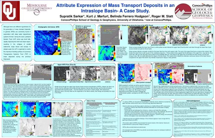
NNW SSE Attribute Expression of Mass Transport Deposits in an Intraslope Basin- A Case Study. Seabed MTD2 Top of Mass Transport Deposit Flow B Studied Mass Transport Complex Interval Flow A 0 0 0 0 0 0 0 0 0 Base of Mass Transport Deposit Supratik Sarkar*, Kurt J. Marfurt, Belinda Ferrero Hodgson†, Roger M. Slatt ConocoPhillips School of Geology & Geophysics, University of Oklahoma. † now at ConocoPhillips. Salt Body in South Stratal slices along the base of the MTD/ FlowA Striation or groove at the base of MTD Although there are different hypotheses for the generation of mass transport deposits, in general, MTDs are commonly found in association with deep water depositional systems formed during the early Lowstand System Tract (LST) when sea level falls, rapidly exposing the shelf and slope region, resulting in the collapse of shelfal sediments, slope failure and slumps. In deeper water the LST is expected to overlie the maximum flooding surface of a previous Transgressive Systems Tract (TST) or shale deposited during the previous Highstand. Flow B Direction Salt Body in West Stratigraphic Unit below MTD A Flow B Direction A A Flow B Direction Flow B Direction A N N’ fault fault Flow A Direction Flow A Direction fault Flow A Direction Flow A Direction fault fault Groove/ striation fault fault fault Amp Amp Amp Amp Amp Amp fault High High High High High High fault fault Root Mean Square amplitude(RMS)computed 400 ft below the base of MTD. The low amplitude deposits may have been deposited during the previous TST. A’ A’ A’ N A’ N N N 1.6 Km 1.6 Km 1.6 Km 1.6 Km RMS coherent energy 1.6 Km eigenstructure coherence RMS RMS RMS RMS RMS generalized Sobel filter variance Flow B Direction N Root Mean Square amplitude(RMS)computed at the base of MTD. The flow conduits of both Flows A and B grow towards the Southwest. Green arrows indicate the lower flow (Flow A ) while yellow arrows indicate the upper flow (Flow B) which cuts down through the lower flow. Cyan arrows indicate arcuatetoe-thrust faults 0 0 0 0 0 0 Flow A Direction Green arrows indicate a broader conduit for the lower flow from the north eastern side. The axis of the upper flow forms a canyon-like conduit that erodes the lower flow as well as part of the underlying sequence. These stratal slices suggest that the direction of the upper flow may also be from north east. We can see only part of the conduit in the available data set. The wings of the upper flow of the MTD are also erosive, but the flow energy is less. We can easily delineate the edges of the two flows. The stratal slices indicate the relatively continuous nature of the lower flow as compared to the upper flow which may indicate mass flow of clayey or silty particles. N 1 Km N N’ Generalized Sobel filter L L’ P Flow direction Upper MTD Flow (Flow B) K K’ Flow direction P P’ Horizon slice through Sobel filter Q’ Anomalous features x Y 0 0 0 0 Rotated Fault Blocks K x Q’ x x Q Q x P’ 1.6 Km Coherent Energy 1.6 Km Coherent Energy Coherent Energy Amp Grad Amp Grad Coherence Coherence Curvature Curvature Seismic Seismic Variance Variance Variance Sobel Sobel Sobel Sobel Sobel N Seismic Seismic +ve +ve Max Max Max Max Max Max Max High High Max Max Max +ve +ve High High High Generalized Sobel filter Max Max K’ L Vertical slice through seismic N N 2 Km 2 Km 2 Km 2 Km N N N 2 Km 2 Km 2 Km 2 Km 2 Km 2 Km 2 Km 2 Km 2 Km N eigenstructure coherence coherent energy generalized Sobel filter variance RMS amplitude Most positive curvature Y Y Y Y 1.6 Km N 1.6 Km N 1.6 Km L’ 1.6 Km N Low Low Low -ve -ve Min Low Min Min Low -ve -ve Min Min Min Min Min Min Min Min Min Most positive curvature Crossline amplitude gradient Coherent energy A series of toe-thrust faults cut through the mass transport deposit which are illuminated by horizon slices through eigenstructure coherence, variance and the generalized Sobel filter attibute volumes. The toe-thrust faults exhibit the same arcuate-shaped profile perpendicular to the direction of flow described in a different setting by Posamentier and Walker (2006). The fault blocks are rotated with the base of the mass transport deposit acting as the decollement surface. Our area of interest is confined by salt in all directions including the south western direction, such that the flow was not able to move a long distance and a thrust situation developed after entering the minibasin. Most of the faults in the studied zone were probably generated by the processes within the MTD. These faults were reactivated during the salt activity and consequently most of the faults have been extended beyond the MTD. Rms amplitude RMS amplitude continuity as well as positive features in the most positive curvature volume indicate a new flow direction in flow unit A. This is significant as this pattern continues in the upper unit. We suspect that thedepositional axes within the basin changed the sedimentation pattern, perhaps by the MTD filling the basin. Several high amplitude blocks showing bright spots in the seismic amplitude data that trend as a NNE- SSE arc (dashed cyan line), indicating their transport direction. These high amplitude bodies are seen near the top of the mass transport deposit or top of the flow A. These features might be slide blocks from the shelf region or sand blocks deposited within the MTD from a sandy debris flow which came from the NNE. The strengths and confined character of these bright spots suggest that they are hydrocarbon-charged sand bodies. Such bright spots are often observed in MTDs. If these bodies are sufficiently large, they may be considered for commercial exploration, otherwise they should be considered to be a potential drilling hazard. Stratal slices through the upper layer shows chaotic texture characteristic of MTDs. Indeed, the flow is so chaotic that the attributes cannot discriminate between internal discontinuities and the discontinuities associated with bounding faults. The flow direction is not clear in these images. We interpret the difference seen in the two flows as the magnitude of the failure activity, flow energy and possibly the origin of the flows. Conclusions Acknowledgement Table of Tools Stratigraphic unit above MTD • In general, MTDs are characterized as package or relatively chaotic reflections bounded by an upper and lower surface which may cut into previously depositied sediments. • Seismic attributes quantify these patterns allowing us to identify different MTD components: • coherence, variance and Sobel filter attributes delineated the overall extent of largely chaotic MTDs, • toe thrusts are well-delineated by coherence, variance and Sobel filter attributes, • glide tracks associated with outrunner blocks are often seen on dip magnitude, dip azimuth, coherence, and other attributes. Glide tracks are rare in our data volume, and • gas-charged sand blocks can be seen on RMS amplitude, coherent energy, and coherence volumes, and appear to be carried along within the MTD. • Depositional axes and sediment fairways of the minibasinappear to have change with the rapid basin-filling by the MTD. • The erosive nature of MTDs may decrease the original volume of the reservoir facies and compartmentalize a previously contiguous reservoir, • MTDs often provide lateral and vertical seal, • the evacuated area of the MTDs may provide accomodation space for subsequent sediment Low-stand fan accumulation We want to acknowledge Hess Inc., for the use of their deepwater GOM data volume for research and education and Schlumberger for providing the Petrel Software, in which the interpretation was done. We also want to acknowledge Ha Mai and Kui Zhang, ConocoPhillips School of Geology and Geophysics at the University of Oklahoma for helping extracting attributes and software expertise Backfilled Feeder channel 2.5 A A’ Backfilled Feeder channel 5 Reference fault Flow axis of FlowB Beaubouef, R.T., and S.J. Friedmann, 2000, High-resolution seismic/sequence stratigraphic framework for the evolution of Pleistocene intra slope basins, Western Gulf of Mexico: Depositional Models and reservoir analogs, in P., Weimer, R.M., Slatt,J.L., Coleman, N., Rosen, C.H., Nelson, A.H., Bouma, M., Styzen, and D.T., Lawrence,eds., Global deep-water reservoirs: Gulf Coast Section-SEPM Foundation 20th Annual Bob F. Perkins Research Conference, 40-60. Chopra, S., and K.J. Marfurt, 2007, Seismic Attributes for Prospect Identification and Reservoir Characterization: SEG Geophysical Developments Series No. 11. Ferrero- Hodgson, B., 2007, An integrated 3d Seismic Sequence-Stratigraphic Analysis of the Pleistocene Strata Above Baldpate Field, Garden Banks, Deep Water Gulf of Mexico : M.S Thesis, University of Oklahoma, Norman, Oklahoma. Okuma, A.F., R.R. Pressler, D.B. Walker, K. Kemp., Baldpate Field Exploration History, Garden Banks 260, Gulf of Mexico in in P., Weimer, R.M., Slatt,J.L., Coleman, N., Rosen, C.H., Nelson, A.H., Bouma, M., Styzen, and D.T., Lawrence,eds., Global deep-water reservoirs: Gulf Coast Section-SEPM Foundation 20th Annual Bob F. Perkins Research Conference. Oyedele, O., 2005, 3D High Resolution Seismic Imaging of Middle- Late Quaternary Depositional Systems, Southeast Green Canyon, Sigsbee Escarpment, Gulf of Mexico : M.S Thesis, University of Houston, Houston, Texas. Posamentier, H.W., and R.G. Walker, 2006, Deep-Water Turbidites and Submarine Fans: SEPM Special Publication No. 84. Weimer, P., and R.M. Slatt, with contributions by Bouroullec, R., R. Fillon, H. Pettingill, M. Pranter and G.Tari, 2006, Petroleum Geology of Deepwater Settings: AAPG Studies in Geology No.57 AAPG Datapages Discovery Series No.8. fault 7.5 N fault fault N N N 10 GeneralisedSobel Filter Depth (Kft) RMS amplitude In contrast to the MTD, the overlying deposits are characterized by continuous reflection events. RMS amplitude indicates a thick sheet deposit. The feeder channels of the sheet can be observed at a shallower level and is characteristic of early LST after the deposition of a MTD. The fact that the feeders are above the sheet indicates they were open during sheet deposition and later backfilled during sea level rise. The internal texture contains a smaller network of channels of the sheet deposit and a sediment fairway from the NNE (indicated by pink arrows), which can be observed from the inline amplitude gradient attribute, eigenstructure coherence and generalized Sobel filter. Note increased reflector continuity towards the top of MTD flow B. We interpret this continuity as either deposition of suspended sediments after failure or as better-sorted deposits trailing the slump front. 12.5 15 17.5 1.6 Km 20 N Variance Inline amplitude gradient