Download
1 / 53
1.25k likes | 5.11k Views
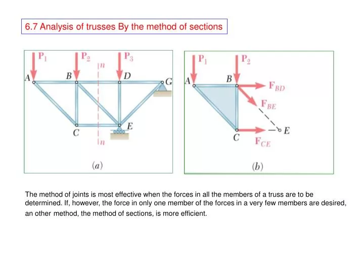
6.7 Analysis of trusses By the method of sections. The method of joints is most effective when the forces in all the members of a truss are to be determined. If, however, the force in only one member of the forces in a very few members are desired,

E N D
6.7 Analysis of trusses By the method of sections The method of joints is most effective when the forces in all the members of a truss are to be determined. If, however, the force in only one member of the forces in a very few members are desired, an othermethod, the method of sections, is more efficient.
Assume for example, that we want to determine the force in member BD of the truss shown in figure 1(a). To do this, we must determine the forces with which member BD acts on either joint B or joint D. If we were to use the method of joints, we would choose either joint B or joint D as a free body. However, we can also choose as a free body a larger portion of the truss, composed of several joints and members, provided that the desired force is one of the external forces acting on that portion. If, in addition, the portion of the truss is chosen so that there is a total of only three unknown forces acting upon it, the desired force can be obtained by solving the equations of equilibrium for this portion of the truss. In practice, the portion of the truss to be utilized is obtained by passing a section through three members of the truss, one of which is the desired member, that is, by drawing a line which divides the truss into two completely separate parts but does not intersect more than three members. Either of the two portions of the truss obtained after the intersected members have been removed can then be used as a free body. In figure 1 (a), the section nn has been passed through members BD, BE, and CE, and the portion ABC of the truss is chosen as the free body ( figure 1b). The forces acting on the free body are the loads P1 and P2at points A and B and the three unknown forces FBD, FBE, and FCE. Since it is not known whether the members removed were in tension or compression, the three forces have been arbitrarily drawn away from the free body as if the members were in tension.
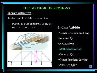
Sample problems 6.2 Determine the force in members EF and GI of the truss shown.
= 0 Free body : Entire Truss. A free body diagram of the entire truss is drawn; external forces acting on this free body consist of the applied loads and the reactions at B and J. We write the following equilibrium equations.
Force in member EF : Section nn is passed through the truss so that it intersects member EF and only two additional members. After the intersected members have been removed, the the left hand portion of the truss is chosen as a free body. Three unknown are involved; to eliminate the two horizontal forces, we write The sense of FEF was chosen assuming member EF to be in tension ; the negative sign obtained indicates that the number is in compression. FEF = 22.5 kN
= 0 FGI = 46.0 kN Force in member GI . Section mm is passed through the truss so that it intersects member GI and only two additional members. After the intersected members have been removed, we choose the right-hand portion of the truss as a free body. Three unknown forces are again involved; to eliminate the forces passing through point H, we write
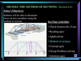
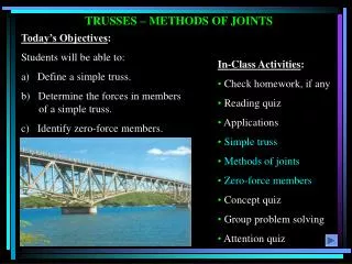
Sample problems 6.3 Determine the force in members FH, GH, and GI of the roof truss shown
FG 8 m α = 28.07º 0.5333 = tan α= = 15 m GL • SOLUTION: • Take the entire truss as a free body. Apply the conditions for static equilib-rium to solve for the reactions at A and L. 30 m
Pass a section through members FH, GH, and GI and take the right-hand section as a free body. • Apply the conditions for static equilibrium to determine the desired member forces. Force in member GI
Force in member FH Force in member GH 15
Problems 6.42 A Warren bridge truss is loaded as shown. Determine the force in members CE, DE and DF
Kx Ay 3kN Ky 3kN FBD Truss
B 5m D FDF 6m Kx FDE E A 5m C FCE Ay 3kN Ky 3kN 4.2kN 3kN 5 13 12
B 5m D FDF 6m Kx FDE E A 5m C FCE Ay 3kN Ky 3kN 4.2kN 3kN
Frames and machines are structures with at least one multiforce member. Frames are designed to support loads and are usually stationary. Machines contain moving parts and are designed to transmit and modify forces. • A free body diagram of the complete frame is used to determine the external forces acting on the frame. • Internal forces are determined by dismembering the frame and creating free-body diagrams for each component. 6.10 Analysis of a Frame • Forces on two force members have known lines of action but unknown magnitude and sense. • Forces on multiforce members have unknown magnitude and line of action. They must be represented with two unknown components. • Forces between connected components are equal, have the same line of action, and opposite sense.
Some frames may collapse if removed from their supports. Such frames can not be treated as rigid bodies. • A free-body diagram of the complete frame indicates four unknown force components which can not be determined from the three equilibrium conditions. • The frame must be considered as two distinct, but related, rigid bodies. 6.11 Frames which cease to be rigid when detached from their support • With equal and opposite reactions at the contact point between members, the two free-body diagrams indicate 6 unknown force components. • Equilibrium requirements for the two rigid bodies yield 6 independent equations.
Sample problem 6.4 In the frame shown, members ACE and BCD are connected by a pin at C and by the link DE. For the loading shown, Determine the force in link DE and the components of the force exerted at C on member BCD
SOLUTION: • Create a free-body diagram for the complete frame and solve for the support reactions.
Members. We now dismember the frame. Since only two members are connected at C, the components of the unknown forces acting on ACE and BCD are, respectively, equal and opposite and are assumed directed as shown. We assume that link DE is in tension and exerts equal and opposite forces at D and E, directed as shown. Free Body : member BCD Using the free body BCD, we write FDE = 561 N C From the signs obtained for Cx and Cy we conclude that the force components Cx and Cy exerted on member BCD are directed, respectively, to the left and up. We have Cy = 216 N Cx = 795 N
Check Free body : member ACE ( check ) The computations are checked by considering the free body ACE. For example,
Sample problem 6.5 Determine the components of the forces acting on each member of the frame shown.
Free body : Entire Frame. Since the external reactions involve only three unknowns, we compute the reactions by considering the free body diagram of the entire frame. F = 1800 N Ey = 600 N Ex = 0 FBD
Members. The frame is now dismembered; since only two members are connected at each joint, equal and opposite components are shown on each member at each joint. Free Body : Member BCD Cy = + 3600 N By = + 1200 N We note that neither Bx nor Cx can be obtained by considering only member BCD. The positive values obtained for By and Cy indicate that the force components By and Cy are directed as assumed
Free Body : Member ABE Bx = 0 Ax = 0 Ay = + 1800 N Free Body : Member BCD Returning to member BCD, we write Cx = 0
Free Body : Member ACF ( Check ) All unknown components have now been found; to check the results, we verify that member ACF is in equilibrium. Check
Sample problem 6.6 2.7 kN 0.75 m 0.75 m 0.75 m 0.75 m 1.8 m A 2.7 kN horizontal force is applied to pin A of the frame shown. Determine the force acting on the two vertical members of the frame.
2.7 kN 2.7 kN 3.0 m 1.8 m Free body: Entire Frame The entire frame is chosen as a free body although the reaction involve four unknowns, Ey and Fy may be determined by writing
2.7 kN 2.25 m 0.75 m 1.5 m 0.75 m 4.5 kN 4.5 kN
2.7 kN 2.25 m 0.75 m 1.5 m 0.75 m 4.5 kN 4.5 kN
90 N 90 N 200mm 50mm 100mm 250mm Problems 6.77 • Determine the force in member AC and the reaction at B when • = 30˚ • = 60˚
FAC 90 N 90 N 90 N 200mm 90 N Bx C D θ 250mm 100mm By 50mm 100mm 250mm Solution
FAC 90 N 90 N 90 N 200mm 90 N Bx C D θ 250mm 100mm By 50mm 100mm 250mm Solution
FAC 90 N 90 N 90 N 200mm 90 N Bx C D θ 250mm 100mm By 50mm 100mm 250mm Solution
6.12 Machines Photo 1 : The lamp shown can be replaced in many positions. By considering various free bodies, the force in the springs and the internal forces at the joints can be determined.
Machines are structures designed to transmit and modify forces. Their main purpose is to transform input forces into output forces. • Create a free-body diagram of the complete machine, including the reaction that the wire exerts. • The machine is a nonrigid structure. Use one of the components as a free-body. • Taking moments about A, 6.12 Machines • Given the magnitude of P, determine the magnitude of Q.
Sample Problem 6.7 A hydraulic-lift table is used to raise a 1000 kg crate. It consists of a platform and two identical linkages on which hydraulic cylinders exert equal forces. (Only one linkage and one cylinder are shown. Members EDB and CG are each of length 2a, and member AD is pinned to the midpoint of EDB. If the crate is placed on the table, so that half of its weight is supported by the system shown, Determine the force exerted by each cylinder in raising the create for θ= 60˚ , a = 0.70 m, and L = 3.20 m. Show that the result obtained is independent of the distance d.
Solution The machine considered consists of the platform and the linkage. Its free body diagram includes a force FDH exerted by the cylinder, the weight ½ W, and reactions at E ad G that we assume to be directed as shown. Since more than three unknowns are involved, this diagram will not be used. The mechanism is dismembered and a free body diagram is drawn for each of its component parts. We note that AD, BC and CG are two force members. we already assumed member CG to be in compression. We now assume that AD and BC arein tension; the forces exerted on them are then directed as shown. Equal and opposite vectors will be used to represent the forces exerted by the two force members on the platform, on member BDE, and on roller C.
Problem 6.139 Determine the magnitude of the gripping forces exerted along line aa on the nut when two 240-N forces are applied to the handles as shown. Assume that pins A and D slide freely in slots cut in the jaws.
By A 0.03m 0.01m Solution Bx G
240N Cx Ex = 0 Cy 0.09m Ey = 4G 3 0.015m A = G 3 A C E