Download
1 / 51
510 likes | 649 Views
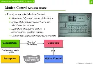
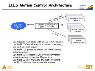
Motion Control. Components. Motion control system includes the following components: GALIL DMC (Ethernet Motion Controller Driver) Drum motion system – Drum driver unit, Drum motor, and encoder MCDU – Motion control / drivers unit Responsible for the motion system of the following: Bridge

E N D
Components • Motion control system includes the following components: • GALIL DMC (Ethernet Motion Controller Driver) • Drum motion system – Drum driver unit, Drum motor,and encoder • MCDU – Motion control / drivers unitResponsible for the motion system of the following: • Bridge • Loader • Buffer • Bridge stepper • Registration (optional) Confidential
DMC Galil Board Confidential
DMC Galil Board (Cont.) • This board controls four motion axes: • Drum motor – X-axis • Loader motor – W-axis • Buffer motor – Z-axis • Bridge motor – Y-axis • Positioned in the control unit and communicates with the computer network via Ethernet cable. • Controls the motors by sending control voltages and inhibiting signals to the motor drivers. • Encoders monitor the drum, loader, buffer and bridge movement. • The encoder signals are sent back to the GALIL board in order to close the motion loop. Confidential
Drum Driver Unit • Located in the electronic cabinet. • Input operation voltage of 75VAC. • There are 3 LED indicators in the front of the Drum motor driver: • Power – Green LED – indicates power input (75VAC) • Motor out – Green-yellow LEDs – indicates the motor polarity: • Green light – the drum rotates in one direction. • Yellow light – the drum rotates in the opposite direction. • Light is off – The motor is IDLE. • Driver status – Green-red LEDs – indicates the driver status: • Green light – the drum is jogging or in stop mode. • Red light – the drum is idle or there is a driver fault like Overheat /Over voltage. Confidential
Output filter Diode bridge Drum driver Drum Motor 75VAC Capacitor Inhibits and Control signals Encoder Shunt regulator GALIL Board Encoder A+ ,A- ,B+ ,B- and Home signals Drum Motion System Confidential
Drum Driver Unit • The drum driver works similar to the PRESS jet II, but with two additional units: • Shunt regulator – over voltage protection for the drum driver, including the fuse for protection inside the drum driver • Output filter – essential, due to the long cable between the drum driver and the drum motor Confidential
Front view Drum Driver Unit (Cont.) Confidential
Back view Drum Driver Unit (Cont.) Confidential
Drum pulley Encoder system Micro-V belt Tension pulley Drum motor Motor pulley Drum Motion System Confidential
Drum Motion System (Cont.) • The drum motion system components include: • Drum motor • Motor pulley • Drum pulley • Drum encoder • Micro-V belt • Tension pulley Confidential
Drum Motion System (Cont.) • The drum motor rolls the drum pulley. • The micro-V belt, which is stretched by the tension pulley, transfers the movement to the drum pulley. • The micro-V belt is a safe and reliable belt, designed to prevent the belt from sliding off. • An extra belt is rolled on the inner side of the drum pulley. Confidential
Drum Motor Confidential
Drum Motor (Cont.) • This motor rotates the drum. • This motor is controlled by the GALIL DMC Board. • It is placed under the power printing bracket. • In order to have clear and easy access to the motor, the electronic cabinet can be moved away (up to 1 meter) from the printing unit. • The drum motor has a built in taco-generator for over-speed/under-speed indications. Confidential
Reading head Encoder scale Drum Encoder System Confidential
Drum Encoder System (Cont.) • This device is designed to track the drum motion. • A metal ring with a gold encoder scale is attached to the drum. • The encoder scale is divided into reading units, translated to a resolution of ~125,000 pulses/turn. • The encoder optic read head can be adjusted by several adjusting screws. Confidential
Drum Encoder Confidential
Drum Encoder (Cont.) • The drum encoder is placed on the drum itself, near the electronic cabinet side. • The drum encoder consists of three elements: • Strip tracker (RGR) • Optical head • Magnetic detector for drum home interrupt • The encoder read head counts pulses when the drum is rotating. • The home tracker tracks a small metal plate on the drum encoder ring in order to reset the home position. Confidential
MCDU – Motion Control Drivers Unit Confidential
4 Phases Fuse for the Cutter MCDU – Motion Control Drivers Unit (Cont.) Confidential
Inside the unit: STC Board MCDB Board MCDU – Motion Control Drivers Unit (Cont.) Confidential
MCDU – Motion Control Drivers Unit (Cont.) • MCDU includes the following modules: • STC – stepper motors controller • Registration motor controller – optional (not in use) • MCDB (Motion Control Driver Board) controls the following: • Bridge motion • Loader (roller) motion • Buffer motion • Cutter motor • Motion safety • The MCDB also isolates and amplifies each one of the four channels of the motion axis. Confidential
MCDU – Motion Control Drivers Unit (Cont.) • The following Input powers are supplied from the supply unit to the MCDU: • 24VAC – converted to 24VDC inside MCDU • 12VDC – for stepper controller (STC) • 5VDC – for MCDB and STC (optional) Confidential
Diode bridge MCDB 24VAC 24VDC Stepper Motors Motion safety Bridge Motor Cutter Motor Buffer Motor Roller Motor 5VDC STC 12VDC Optional Registration Motor MCDU – Motion Control Drivers Unit (Cont.) Confidential
MCDU – Motion Control Drivers Unit (Cont.) • Connections at the back of the MCDU: • J1 – 24VAC, 12VDC and 5VDC input powers from thesupply unit • J2 – power output for all motors • J3 – controls from control bracket • J4 – control for drum driver • J5 – motion safety Confidential
MCDU – Motion Control Drivers Unit (Cont.) • Motion safety: • Cover switches • Under speed protection • Over speed protection Confidential
MCDU – Motion Control Drivers Unit (Cont.) • Cover switches: • If a cover is opened, the following sequence begins: • All motors are stopped from the RT software. • After a four second timeout, the GALIL software (GALIL limit switch) stops all motors. • After a timeout of another four seconds, the hardware carries out a full stop of the motors by disabling the motion drivers. Confidential
MCDU – Motion Control Drivers Unit (Cont.) • Under speed protection • The main purpose is to protect the drum from overheating. • There are two separate systems for under speed protection: • Tacho generator – generates voltage, proportional to the drum motor speed. • If the voltage is less than the preset value in the Motion Control Drivers board inside the MCDU, under speed protection is enabled and automatically shuts down the power to the IR units to protect the drum. • Under speed sensor – monitors the drum movement. Confidential
Tacho generator MCDU Control unit Control unit Electrical cabinet Printer signal bracket Under speed sensor Complete shut down of IR and Hot air units MCDU – Motion Control Drivers Unit (Cont.) Confidential
MCDU – Motion Control Drivers Unit (Cont.) • Over speed protection • Tacho generator generates voltage, proportional to the drum speed. If the voltage exceeds the preset value in the Motion Control Drivers Board inside the MCDU, over speed protection is enabled and automatically shuts down the 75VAC power to the drum driver (provided inside the supply unit). • There is an over speed push button in the front of the MCDU, which must be reset in case of over speed. Confidential
Control unit MCDU Printer signal bracket Tacho generator Supply unit Complete shut down of 75VAC for drum driver MCDU – Motion Control Drivers Unit (Cont.) Confidential
MCDU – Motion Control Drivers Unit (Cont.) • Indications and fuses: • Over speed release push button • 24VDC indication light for motion driver board • 24VDC indication light for cutter motor and registration motor (not in use). The light indication is connected after the fuse protection. • Light indication for cover switches • Light indication for over speed • Light indication for under speed (Tacho) Confidential
MCDU – Motion Control Drivers Unit (Cont.) • Light indication for under speed (proximity) • Four light indications for stepper motor, one for each phase • Four light indications of output voltage for the following motors: • Bridge • Buffer • Loader • Cutter motors Lights for these motors change from green to yellow according to the voltage polarity (indicates the motor movement direction). Confidential
MCDU – Motion Control Drivers Unit (Cont.) Confidential
Bridge Steppers Motion • STC controller, which is located inside the MCDU controls the two stepper motors on the bridge. • Via the computer, the operator can control the bridge backwards/forwards movement relative to the drum. Confidential
Bridge Stepper Motors Confidential
Bridge Stepper Motors (Cont.) • There are two stepper motors on the bridge. • These motors enable the bridge Z-axis motion towards and away from the drum. • Each motor on each side of the bridge is a stand-alone unit. • Each motor receives the same control signal from the STC board, which is located inside the MCDU. • The two motors are not connected in their motion. Confidential
Bridge Limit Sensors • There are four sensors on the bridge Z axis: • Two forward – proximity sensors • Two backwards – mechanical sensors • The two forward sensors are in plot position and the two backward ones are in maintenance position. • These sensors are connected to the STC board, enabling it to detect the motion limits of the bridge stepper motors. Confidential
Backward limit switch Forward proximity sensor Bridge Backward/Forward Switches Confidential
Print motor Linear encoder Motor encoder Bridge Motor and Encoder Confidential
Bridge Motor and Encoder (Cont.) • This motor enables the motion of the bridge printing axis. • It is controlled by the GALIL DMC Board. • A linear encoder controls its operation. • The linear encoder has a built in index (bridge home). • The encoder signal is sent to the GALIL to indicate the motor speed and location. • The bridge motor and encoder are placed on the edge of the right bridge roll in the chassis. • The motor has a belt, transferring its rotation to the bridge roll. Confidential
Roller Motor and Encoder Connections Confidential
Loader roll Roller motor & encoder Behind the chassis wall Pulley and Timing belt Roller Motor and Encoder Confidential
Roller Motor and Encoder (Cont.) • This motor enables the pulling of the substrate towards the buffer in the loading system. • It is controlled by the GALIL DMC Board. • A built-in encoder controls the motor operation. • Controlling the roller motor movement enables the defining of the media length, which will be inserted towards the buffer. Confidential
Roller Motor and Encoder (Cont.) • The encoder signal is sent to the GALIL to indicate the motor speed and monitor the movement. • The roller motor and encoder are placed in the loading system above the buffer. • It has a belt, which transfers its rotation to the loader roll. Confidential
Buffer belts Timing belt Buffer motor encoder Buffer Motor and Encoder Confidential
Buffer Motor and Encoder (Cont.) • This motor rolls the buffer belts to enable the substrate to roll in and out from the buffer. • It is controlled by the GALIL DMC Board. • The buffer motor has a built in encoder in order to control the substrate length, which goes out from the buffer output tray towards the drum’s grippers. • The encoder signal is sent to the GALIL to indicate the motor speed and direction. • The buffer motor and encoder are placed above the buffer. Confidential
Roller, motor, encoder interface board Buffer, motor, encoder interface board Interface Boards Confidential
Interface Boards (Cont.) • Each encoder has its own interface board. • The interface board is connected to the encoder, and eventually to the GALIL DMC Board. Confidential
To Cutter Motor MCDU Cutter flag right-to I/O (type I) Cutter flag left-to I/O (type I) Left Cutter Limit Switch Right Cutter Limit Switch Cut command from I/O (type I) controller MCDU - Cutter System Confidential