Download
1 / 23
250 likes | 422 Views
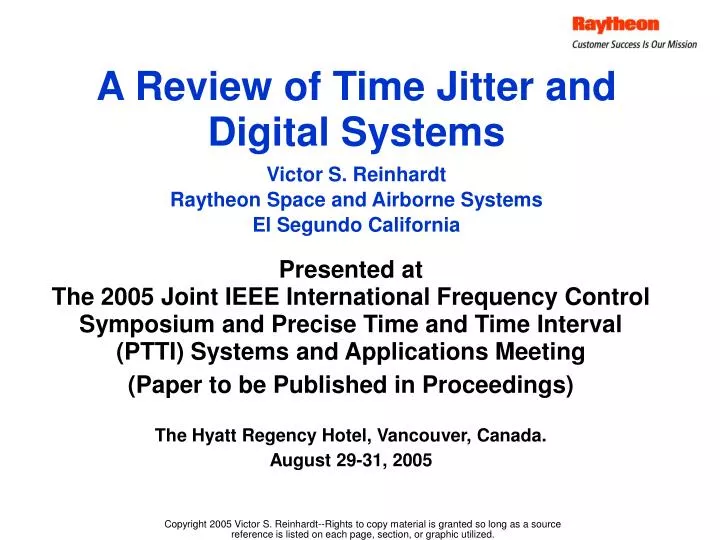
A Review of Time Jitter and Digital Systems. Presented at The 2005 Joint IEEE International Frequency Control Symposium and Precise Time and Time Interval (PTTI) Systems and Applications Meeting (Paper to be Published in Proceedings). Victor S. Reinhardt Raytheon Space and Airborne Systems

E N D
A Review of Time Jitter and Digital Systems Presented atThe 2005 Joint IEEE International Frequency Control Symposium and Precise Time and Time Interval (PTTI) Systems and Applications Meeting (Paper to be Published in Proceedings) Victor S. Reinhardt Raytheon Space and Airborne Systems El Segundo California The Hyatt Regency Hotel, Vancouver, Canada. August 29-31, 2005
Introduction — Overview • Time jitter is an important parameter for determining the performance of digital systems • This paper will review the mechanics how time jitter impacts the performance of such systems ~ Agenda ~ • Introduction & overview • A statistical framework for later discussions • Discuss time jitter impact by category of digital system • Conclusions-Summary Note: This presentation has been updated based on audience comments
Categories of Digital Systems for Discussing Impact Time Jitter Synchronous • Categories somewhat overlap • Synchronous data transfer • Common clock distributed along with data • Cancels most direct effects from clock oscillator • Gate timing jitter generates bit errors • Asynchronous data transfer • Only data distributed & local clocks regenerated • Includes digital communications systems • Additional bit errors caused by relativemaster-local clock oscillator (MO-LO) jitter • Digital sampling • Analog signals are sampled & digitized or visa versa • A/Ds & D/As: Sampling clock jitter generates noise power • Communications systems decision circuits:Sampling clock jitter causes bit error rate (BER) degradation Dig Dig Data Clock Asynchronous Dig Dig Data Clock Clock PLL Digital sampling Analog Digital Data A/D Voltage Clock
Soft Errors & Noise Power Time JitterCauses BER Degradation & Generates Noise Power V V t Clock Types of Degradation Caused by Time Jitter • Hard bit errors • Direct bit errors without any other factors involved • Data clock jitter moves clock edge out of correct data transfer window • Soft bit errors (BER degradation) • Increase in BER when thermal noise is present (no errors when no thermal noise) • Occur in symbol (or bit) decision circuits which turn an analog signal into digital symbol stream by sampling • Clock jitter causes BER degradation by generating variations in sampled signal • A/D & D/A noise power • Sampled voltage noise caused by time jitter induced variations • This noise power decreases the effective number of bits (ENOB) of A/Ds & D/As Hard Errors Data Window Data Clock Time Jitter Causes DataTransfer Errors
Defining Time Error in Digital Systems • Two definitions of time error • Data transfer: Time error is between data clock edges & data symbol centers • Digital sampling: Time error is between sampling clock edges and correct analog epoch • Time error broken into two components • Skew = average error • Fixed plus long term and environmental changes • Usually measured by an N-sample mean • Jitter = short term variation • Specified as RMS, peak, or peak-to-peak relative to skew • RMS usually interpreted as N-sample standard deviate • Bit errors function of total error so jitter must reference skew • Noise power caused by jitter alone so reference to skew not important (Skew important for sampling accuracy) Data Transfer Skew Data Clock Jitter Error Digital Sampling Jitter V(t) t Skew Error Total Time Error = Skew + Jitter
A Statistical Frameworkfor Time Jitter & Digital Systems Background for Statistical Approach Chosen • Digital community has historically dealt with time jitter using stationary statistics • The standard variance generally used as the jitter measure • Bandwidth (BW) and non-stationary noise (1/fn noise) issues often not explicitly dealt with • Become important to treat BW & 1/fn issues explicitly because time jitter requirements now in ps & sub-ps regions • Precise time community has historically dealt with BW & 1/fn issues using 2nd difference measures of jitter • But these 2nd difference measures not easily connected to the skew • The statistical framework presented here will attempt to meld both approaches • Will use the standard variance as jitter measure because it directly references the skew • Will rigorously deal with BW and 1/fn noise issues • Will show that the standard variance can be used with 1/fn noisebecause of unique properties of digital systems
Subject ClockReading V(t) = A(t)F(wot+ f(t)) f x t’n t dt Vref(t) = AoF(wot) tn t fref = 0 By Definition RefClockReading F(.) = Periodic Function ClockReading= Cyclesin 1/fo units Basic Clock fo Freq Source Cycle Counter Definition of Two Associated Time Error Variables • Clock reading (normalized phase) errorx(t) = f(t)/wo • Difference between subject and reference clock readings at same time • x(t) can be considered continuous variable--derived from f(t) • Will use x in presentation • Time (zero crossing) error dt(tn) = t’n – tn – x(tn) • Difference between subject and reference clock edgesat same cycle or period count • Is approximately the negative of x(tn) • x(t) is the derivative of the fractional frequency error y = df/fo = dx/dt = - d(dt)/dt • x preferred because no minus sign
EnsembleAverage <…> = Discrete Samples xn and Jitter Measure Contin-uous x(t) = f(t)/wo N DiscreteSamplesxn Spaced by • N samples xn spaced by interval • xn derived from convolution of continuous x(t) with explicit system phase response function hs(t) • Explicit use of hs(t) will be important • Skew = N-sample arithmetic mean SystemResponsePhasehs(t) • Jitter measure will be N-sampleunbiased standard variance • Ensemble average of the arithmetic mean of N squared1st differences between xn and skew Mx(N) • Has well known convergence problems for 1/f3 noise • Will show is mitigated in digital systems by hs(t)
Closest 2nd Difference Variance For Comparison • Ensemble average of arithmetic mean of N squared 2nd differences of xn’s • More familiarly written in terms of N-sample fractional frequency Allan variance 2y(N,,) * • Well behaved for 1/f3 noise • But eliminates direct reference to skew Mx(N) • * See: B. E. Blair, Ed, Time and Frequency Fundamentals, NBS Monograph 140, U. S. Govt. Printing office, 1974 (CODEN:NBSMA6), p 166.
Sx(f) (double sideband PSD) |Hs(f)|2Kx(f) Hs(f) can have LF cut-off Integration Region Frequency from Carrier f Spectral Integral of Variances s2xd(t,N) & s2xa(t,N) • Kernel Kx(f) = Kxd(f) or Kxa(f)Describes the variance • Why a kernel? Kx(f) for N samples cannot be represented by the square of a single response function • Sx(f) = Double-sideband (DSB) power spectral density (PSD) of x(t) Describes the noise • Lx(f) = ½Sx(f) = SSB PSD • Hs(f) = DSB Fourier transform of hs(t) Describes the system • System assumed linear in phase • Hs(f) can contain high & low frequency BW cut-offs SystemResponse|Hs(f)|2 System Properties VarianceKernelKx(f) Variance Properties Sx(f) sx2
Kxd & Kxa vs f f = 1/N Kxd f2 dB f2 Kxa f4 Log(f) (N=100) Kernels of s2xd(t,N) & s2xa(t,N) • Standard Variance s2xd(t,N) • For Nf << 1: Kxd(f) f2 • Converges for Sx(f) = 1/f0 … 1/f2 • Also converges for 1/f3 & 1/f4 if Hs(f) contains appropriate highpass filter • 2nd Difference Variance s2xa(t,N) • For Nf << 1: Kxa(f) f4 • s2xa converges for Sx(f) = 1/f0… 1/f4
Properties of s2xd(t,N) as N • When N Kxd 1 and 2xd(,N) Single point standard variance 2x-std • Again 2x-std can exist for 1/fn noise because of |Hs(f)|2 • When there are mathematical difficulties with 2x-stdcan fall back on s2xd(N) with large but finite N • |Hs(f)|2 often approximated by square bandpass filter • Then • fl = low frequency cut-off –fh = high frequency cut-off
Impact of Time Jitter on Digital Systems by Category • Will use framework just presented to discuss impact by category • Synchronous data transfer systems • Asynchronous data transfer systems • Digital sampling systems • Will show that s2xd(, N) & s2x-std can be used because of properties of these systems
Common Clock OscillatorFrequency = fo DigitalSubsystem DigitalSubsystem Data Gate Noise BW = fg Common Clock Delay m Time jitter & Synchronous Systems • Common clock oscillator distributed to all units • Cancels most direct clock oscillator effects • There is some residual high pass filtered oscillator noisedue to time misalignment between clocks • Hs(f) = 4sin2(m) f2 for fm << 1 • Both gate and residual oscillator noise can be modeled by white plus 1/f noise terms Sx(f) = g0(1 + fk/f) • fk = 1/f or flicker knee freq where 1/f noise PSD = white noise PSD • Hs(f) can be approximated by square lowpass filter • fl = 0 – fh = fg= gate noise bandwidth • Note fh is not equal to fo the clock frequency but fg • Usually fg >> fo so aliasing of white noise is a major issue
Aliasing of White Noise in Digital Systems Analog noise Sx(f) • Aliasing occurs because discrete digital system is equivalent to system sampled at fo • Logic sees noise frequencies up to fh = fg (and fg >> fo) • The sampling aliases the original Sx(f) over BW fg into BW fo • This aliasing multiplies white Sx(f) by factor of fg/fo • Aliasing can also impact counter measurementsbecause of large counter fh compared with fo • Counter fh may be much higher than gate BW fg Sx multiplied by (fg/fo) due to aliasing Original Sx(f) Sampled noisehas same in BW fo . . . . fo 2fo 3fo fg . . . To 2To 3To nT0 Freq from carrier Clock Cycles
For Synchronous Systems1/f Effects are Negligible • For Sx(f) = g0(1 + fk/f) can calculate s2xd(, N) • Time Tk = N where 1/f noise term = white noise term given by • For all logic types Tk >>> Life of universe and 1/f noise can be ignored for all practical Nt values • Thus for synchronous systems need use only white noise component of Sx(f) [N >>1]
Time Jitter & Asynchronous Systems(Shown as Communications System) Transmitter Link Response Hh(f) Receiver • Data sent between units without clock * • Clock recovery phase locked loop (PLL) regenerates clock & tracks Rx clock LO to Tx clock MO • Because of this there is additional MO-LO clock oscillator jitter • System response has two components • Clock recovery PLL response Hp(f)--provides low frequency cut-off at loop BW Bp • Tx-Rx link response Hh(f)--provides high frequency cut-off • fh Rs/2 (Rs = Symbol rate) for communications systems • Also other asynchronous systems such as RS-422 • fh less easily specified (Worst case fh = fg) Modulated Data TxDigital Mod-ulator TxFilter RxFilter De-Mod Deci-sion RxDigital Clock Master Osc (MO) Clock Local Osc (LO) Clock Recovery PLL Hp(f)Loop BW = Bp * See: Victor S. Reinhardt, The Calculation of Frequency Source Requirements for Digital Communications Systems, Proceedings of the IEEE International Frequency Control Symposium 50th Anniversary Joint Conference, 24-27 August, 2004, Montréal, Canada. Slides at http://www.ieee-uffc.org/freqcontrol/Reinhardt_files/frame.htm
Sx(f) (Sum of all Clocks ) |1-Hp(f)|2|Hh(f)|2 • f4 for 2nd Order PLLs Variance Integration Region fh fl = Bp Frequency from Carrier f Standard Variance for MO-LO Jitter • Sx(f)= sum of PSD’s of all oscillatorsin Tx-Rx link • Hp(f) = clock recovery PLL response function • Hh(f) = DSB complex envelope response function of Tx-Rx link • |1 – Hp(f)|2 provides LF cut-off at PLL loop BW Bp • 2nd PLL will cancel 1/f3 noise completely • 1st order PLL will leave residual 1/ffor 1/f3 Sx(f) • But has negligible effect on s2xd (,N) (See synchronous systems) • However susceptible to cycle slipping • |Hh(f)|2 provides high freq cut-off fh
RMS Jitter Reqs for QPSK @ 0.1 dB BER Deg -5 Time Jitter & Digital Sampling -6 -7 TimeJitter -8 V(t) -9 GeneratesRandomVariationsinSampledVoltage -10 Jitter - log(sec) -11 1-bit -12 t 30 40 50 60 70 80 90 0-bit Timing Skew Symbol Rate - dBHz Time Jitter & Digital Sampling • Time jitter generates random variations in sampled voltage • In communications systems decision circuits • Random voltage variations interact with thermal variations to produce BER degradation • BER degradation is derived using a Gaussian xn with s2x-stdfrom asynchronous transfer • Time jitter requirements approach 1 ps at > GHz symbol rates
2A Noise Power dV Time Jitter x Phase Jitter In A/Ds & D/As Time JitterGenerates Noise Power • Noise power consists of random variations in sampled voltage generated by slope modulation of signal • For sinewave signal * SNRjitter-1sf2 = ws2 sx-std2 = sV2/Ps • fh = fg unless otherwise restricted • Note SNRjitter is independent ofnumber of digitized bits • Means SNRjitter reqs more severe asnumber of bits increases • Can convert SNRjitter to an ENOB by • By equating SNRjitter to quant error SNR • And assuming a given signal power level • Voltage PSD for white-x noise SV(f) (fh/fo) ws2goPs (sx-std2 = fhgo) Sinewave (SW) Signal V(t) = A sin(wst+ f) • Near Zero: f = wsx = dV/A • s = 2fs =SW Ang freq • Ps = SW power = A2/2 • fo = Sampling clock freq * see: Analog Devices, Mixed-Signal and DSP Design Techniques, Section 2, Sampled Data Systems, http://www.analog.com/Analog_Root/static/pdf/dataConverters/MixedSignal_Sect2.pdf, p35
20 18 TimeJitter 16 0.1 ps 14 ENOBtot for 10 dB BO 1 ps SNRtot-dB - dB 12 10 ps 10 0.1 ns 8 1 ns 6 Log10(SW Freq – Hz) ENOB Limits from Time Jitter Generate Stringent Requirements • ENOBtot values generated from * • Signal level @ 10 dB back-off (BO) from full scale (FS) • Typical BO for complex signals • SNRtot = 2SNRjitter = SNRquant • Assumes SNRjitter = SNRquant • Is major limiting issue for high speed A/Ds and D/As * Differs from ENOB defined inother sources which use fullscale signal level • 10 dB BO more realistic(& conservative)
Noise Power & Non-White noise • For non-white noise the appropriate s2xd(,N) & s2x-std can be generated as follows • Synchronous sampling system • Sampling clock derived directly from the analog signal clock • See s2x-std from synchronous data transfer • Asynchronous sampling system • Sampling clock locked to analog signal clock though PLL (or equivalent) • For MO-LO jitter see s2x-std from asynchronous data transfer • For gate jitter see s2x-std from synchronous data transfer • Total variance is sum of the above • Unsynchronized sampling system • Independent sampling and signal clocks • For up to 1/f2 noise can use s2xd(,N) • There will be divergence and accuracy issues from 1/f3 noise unless there is calibration in system that has implicit low frequency cut-off
Conclusions--Summary • Should explicitly use system response hs(t) so standard variances s2xd(,N) & s2x-std can be used with 1/fn noise • For synchronous transfer need only use white noise component of Sx(f) for s2xd(,N) & s2x-std • Common clock cancels out oscillator 1/f2 and 1/f3 noise • 1/f noise term negligible compared with white noise term • Aliasing significantly increases white noise PSD • Time jitter causes hard errors • For asynchronous transfer there is an additional MO-LO jitter term • Has oscillator 1/f2 and 1/f3 noise components • PLL loop BW provides LF cut-off so s2xd(,N) & s2x-std exists • Time jitter also causes BER degradation (soft errors) • Noise power in digital sampling (A/Ds & D/As) • Limits effective number of bits (ENOB) • Clock jitter is critical limitation on high speed A/D & D/A performance