Download
1 / 46
460 likes | 615 Views
Learn about the Sierpinski Gasket shape, OpenGL API, 2D graphics, and 3D world representation in this programming tutorial. Understand primitives, attributes, colors, and viewing control functions. Develop sophisticated two-dimensional programs without user interaction.

E N D
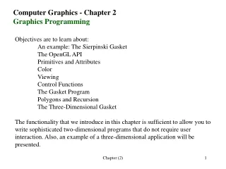
Computer Graphics - Chapter 2 Graphics Programming Objectives are to learn about: An example: The Sierpinski Gasket The OpenGL API Primitives and Attributes Color Viewing Control Functions The Gasket Program Polygons and Recursion The Three-Dimensional Gasket The functionality that we introduce in this chapter is sufficient to allow you to write sophisticated two-dimensional programs that do not require user interaction. Also, an example of a three-dimensional application will be presented. Chapter (2)
The Sierpinski Gasket The Sierpinski Gasket is an interesting shape that has a long history and that is of interest in areas such as fractal geometry. The gasket is defined recursively and randomly, but it has some properties that are not completely random. Suppose we start with three vertices in the x-y plane. Assume that each vertex is defined by a pair of (x,y) as; (x1, y1), (x2, y2), and (x3, y3). Here are the steps to construct the Gasket: 1. Pick an initial point at random inside the triangle 2. Select one of the three vertices at random. 3. Find the point halfway between the initial point and the randomly selected vertex. 4. Display this new point by putting some sort of marker, such as a small circle, at its locations. 5. Replace the initial point with this new point. 6. Return to step 2. Chapter (2)
The Sierpinski Gasket – cont. P0 is the initial point, P1 and P2 are the first two points generated by our algorithm. If we continue with this algorithm, what will we get at the end? A possible form for the graphic program might be this: main ( ) { initialize_the_system(); for(some_number_of_points) { pt = generate_a_point( ); display_the_point(pt); } cleanup( ); } The final OpenGL program will have a slightly different organization, but will be as simple as this one. Chapter (2)
Few remarks The Pen-Plotter Model is the graphics is a two-dimensional model used by most early graphics systems. A pen plotter produces images by moving a pen in two orthogonal directions. Such graphics system can be described by: moveto(x,y); // moves the pen to location (x,y) without putting a mark lineto(x,y); // moves the pen to location (x,y) and draws a line Example1: What does the following fragment generate? moveto(0,0); lineto(1,0); lineto(1,1); lineto(0,1); lineto(0,0); Example 2: What does the following fragment generate? moveto(0,1); lineto(0.5,1.866); lineto(1.5,1.866); lineto(1.5,0.866); lineto(1,0); moveto(1,1); lineto(1.5,1.866); Chapter (2)
Few remarks – cont. We are interested in 3-D world, and we have to figure out a way to represent the 3-D world in a 2-d projection view. A point in 3-D space without a value for one of its dimensions is a point in the 2-D space. Thus, a point can be defined as p = (x,y) or p = (x,y,0). We use vertices to define objects, two vortices define a line, three vertices determine either a triangle or a circle, four vertices determine a quadrilateral, and so on. OpenGL has multiple forms for many functions. The vertex function can be defined in a general form as: glVertex* * can represent 2 or 3 characters in the form of nt or ntv: n denotes the number of dimensions. t denotes the data type (integer i, float f, double d, v specifies an array or a pointer). Chapter (2)
Few remarks – cont. In OpenGL, we use types as GLfloat and GLint rather than C like float and int. These types are defined in the header files: #define GLfloat float I ) A 2-D form for a vertex function with integers: glVertex2i(GLint xi, GLint yi) II) A 3-D form for a vertex function with floating-point numbers: glVertex3f(GLfloat x, GLfloat y, GLfloat z) III) Using an array we can save the information for a 3-D vertex: GLfloat vertex[3] Then we can use this to write II as: glVertex3fv(vertex) We can group as many vertices as we wish to make an object. Chapter (2)
Few remarks – cont. Example 1: glBegin(GL_LINES); glVertex2f(x1, y1); glVertex2f(x2, y2); glEnd( ); Example 2: glBegin(GL_POINTS); glVertex2f(x1, y1); glVertex2f(x2, y2); glEnd( ); What is the difference between the above example? Can you write them in array format? Chapter (2)
Sierpinski Gasket – cont. The first thing we need to do is to decide the size of window within which we plan to see the gasket. Suppose we decide to have a 500x500 square with the lower hand corner at (0, 0) for this purpose. The second thing we need to do is to decide how we want to represent the geometric data. We can use separate x,y, z or use an Object Oriented approach. Neither C nor OpenGL are OOL. We can use typedef instead. typedef GLfloat point2[2]; Now we can create a program to randomly create 5000 points each time it is called. Chapter (2)
void display( void ){ typedef GLfloat point2[2]; /* define a point data type */ point2 vertices[3]={{0.0,0.0},{250.0,500.0},{500.0,0.0}}; /* A triangle */ int j, k; int rand(); /* standard random number generator */ point2 p ={75.0,50.0}; /* An arbitrary initial point inside triangle */ glClear(GL_COLOR_BUFFER_BIT); /*clear the window */ for( k=0; k<5000; k++) /* generate 5000 new points */ { j=rand()%3; /* pick one of the 3 vertices randomly */ /* Compute point halfway between selected vertex and old point */ p[0] = (p[0]+vertices[j][0])/2.0; p[1] = (p[1]+vertices[j][1])/2.0; /* plot new point */ glBegin(GL_POINTS); glVertex2fv(p); glEnd(); } glFlush(); /* clear buffers */ } Chapter (2)
Sierpinski Gasket – cont. What else is remaining? 1. What colors are we drawing? 2. Where on the screen does our image Appear? 3. How large will the image be? 4. How do we create an area of the screen - a window – for the image? 5. How much of our infinite pad will appear on the screen? 6. How long will the image remains on the screen? Chapter (2)
#include <GL/glut.h> /* includes GL related functions */ void myinit(void) /* initializing function */ { glClearColor(1.0, 1.0, 1.0, 1.0); /* sets a white background */ glColor3f(1.0, 0.0, 0.0); /* sets the drawing color to red */ /* set up viewing */ glMatrixMode(GL_PROJECTION); glLoadIdentity(); /* identity matrix, to reset coordinates */ gluOrtho2D(0.0, 500.0, 0.0, 500.0); /* 500 x 500 window with origin lower left */ glMatrixMode(GL_MODELVIEW); } Add the Display function here. Chapter (2)
/* Two-Dimensional Sierpinski Gasket */ /* Generated Using Randomly Selected Vertices And Bisection */ void main(int argc, char** argv) { /* Standard GLUT initialization */ glutInit(&argc,argv); /* set a single buffer and use RGB for color interpretation */ glutInitDisplayMode (GLUT_SINGLE | GLUT_RGB); /* Size of window to draw in */ glutInitWindowSize(500,500); glutInitWindowPosition(0,0); /* place window top left on display */ glutCreateWindow("Sierpinski Gasket"); /* window title */ glutDisplayFunc(display); /* display callback invoked when window opened */ myinit(); /* initializes the attributes, sets OpenGL states */ glutMainLoop(); /* enter event loop */ } Chapter (2)
Q2 - Let’s see how we can draw this triangle with sides of size 200 After you did the calculations, write the OpenGL code to draw it. We are using: glOrtho2D(0, 250, 0, 250) x, y x+200, y x + 100, ? Chapter (2)
Coordinate Systems We have talked about vertices x, y, and z, but we haven’t said much about their interpretation. In what unit they are? Where is their origin? The answer to these question is that it is really up to you. The graphics application programmer works in any coordinate system that he/she desires. The user coordinate system, world coordinate system or the problem coordinate system, is independent of the input/output devices. The units on the display coordinate is referred to as the raster coordinates or screen coordinates. This units are always expressed as integers. Chapter (2)
The OpenGL API How do our objects appear on the display? Graphics Functions Our model of a graphics package is a black box. Inputs are functions calls, and Outputs are the graphics sent to our output device. Here are the major functions in OpenGL: 1. Primitive functions 2. Attribute functions 3. Viewing functions 4. Transformation functions 5. Input functions 6. Control functions Chapter (2)
Primitive Functions Defines the low-level objects or atomic entities that our system can display. Depending on the API, the primitives can include points, line segments, polygons, pixels, text, and various types of curves and surfaces. Attribute Functions The primitive functions are the what of an API then the attribute functions are the how. The attribute functions are responsible for: choosing a color to display a line segment choosing a pattern to fill inside a polygon choosing a type face for the title on a graph Viewing Functions Allow us to fix the view and to clip out subjects that are too close or too far away. It allows us to specify various views. Chapter (2)
Transformation Functions Allow us to perform, rotation, translation, and scaling. Input Functions Allow us to deal with devices such as keyboards, mice, and data tables. Control Functions Enable us to communicate with the window system, to initialize our programs, and to deal with any errors that take place during the execution of our programs. Chapter (2)
The OpenGL Interface OpenGL function names begin with the letters gl and are stored in a library usually referred to as GL. GLU is the Graphics Utility Library. Another library GL Utility Toolkit, GLUT, addresses the problems of interfacing with the window system. OpenGL makes heavy use of macros to increase code readability and to avoid the use of magic numbers. Thus, strings such as FL_FILE and GL_POINTS are defined in header (.h) files. We use #include<GL/glut.h> or #include<glut.h> for glut.h, gl.h, and glu.h. Chapter (2)
Primitives and Attributes An API should contain a small set of primitives that all hardware can be expected to support. In addition, the primitives should be orthogonal, each giving a capability unobtainable from the others. A minimal system should support, lines, polygons, and some form of text (strings of characters). Users need more complex primitives to build sophisticated applications. But, a hardware system that can support the large set of primitives probably would not be portable. OpenGL takes an intermediate position. The basic library has a small set of primitives. An additional library, GLU, contains a richer set of objects derived from the basic library. The basic OpenGL primitives are specified via points in space or vertices. Something: like: glBegin(type); glVertex*( … ); .. glEnd( ); Chapter (2)
Primitives and Attributes In OpenGL, there are several options to display line segments, the primitives and their type specifications include: Line segments (GL_LINES) The line-segment type causes successive pairs of vertices to be interpreted as the endpoints of individual segments. Polylines (GL_LINE_STRIP) When successive vertices (and line segments) are to be connected, we can use the line strip or polyline form. Chapter (2)
Polygon Basics The name polygon refers to an object that has a border that can be described by a line loop, but has an interior. Polygons can be displayed several different ways. simple Polygons are either simple or nonsimple. nonsimple Chapter (2)
Polygon Types in OpenGL Polygons(GL_POLYGON) The edges are the same as they would be if we used line loops. Most graphics systems allow you to fill the polygon with a color pattern or to draw lines around the edges, but not both. In OpenGL, we can use the function glPolygonMode to select edges instead of fill (the default). If we want to draw a polygon that is filled and to display its edges, then we have to draw it twice, Once in each mode, or to draw a polygon and a line loop with the same vertices. Chapter (2)
Polygon Types in OpenGL Triangles and Quadrilaterals (GL_TRIANGLES, GL_QUADS) These are special cases of polygons. Using these types may lead to a rendering more efficient than that obtained with polygons. Strips and Fans (GL_TRIANGLE_STRIP,GL_QUAD_STRIP,GL_TRIANGLE_FAN) These objects are based on groups of triangles or quadrilaterals that share vertices and edges. In the triangle strip, each additional vertex is combined with the previous two vertices to define a new triangle. In the QUAD_STRIP, we combine two new vertices with the previous two vertices to define a new quadrilateral. Chapter (2)
Text Text is computer graphics is problematic. There are two forms of text: stroke and raster. The stroke text is constructed the same way as other graphics primitives. We use vertices to define line segments or curves that outline each character. Advantages of having stroke text are: It can be defined to have all the details of any other object, It can be manipulated by our standard transformations, and viewed like any other graphical primitive. A character can be defined once and can be transformed to obtain a desire size or orientation. Postscript fonts are good examples for this type of text. Chapter (2)
Text – cont. Raster text is simple and fast. Characters are defined as rectangles of bits called bit blocks. A raster character can be placed in the frame buffer rapidly by a bit-block-transfer (bitblt). If we use bitblt, then we can modify the contents of the frame buffer directly. The size of characters can be increased by replicating or duplicating pixels. Due to the fact that raster characters are often stored in the ROM, this may create a problem with the portability of some of the characters. glutBitmapCharacter(GLUT_BITMAP_8_BY_13,c) OpenGL does not have a text primitive, however, GLUT provides a few bitmap and stroke character sets that are defined in software and are portable. In the above example, c is the number corresponding to the ASCII characters that we want to display. Chapter (2)
Curved Objects The primitives in our basic set have all been defined through vertices. With the exception of the point type. They all either consist of line segments or use line segments to define the boundary of a region that can be filled with a solid color or a pattern. We can take two approaches to create a richer set of objects: 1) Use the primitives that we have to approximate curves and surfaces. Example: to create a circle simply use a polygon of n sides. More generally, a curved surface can be approximated by a mesh of convex polygons – a tessellation. 2) use the mathematical definitions of curved subjects. Most graphics systems will provide both options. In OpenGL, we can use the utility library GLU for a collection of approximations to common curved surfaces. We also can write our own functions to define new ones. Chapter (2)
void display( void ) { glClear(GL_COLOR_BUFFER_BIT); double angle; int N = 4; glColor3f(0.0, 1.0, 0.0); point2 p1={90,50}, p2; glBegin(GL_LINE_STRIP); for( int I = 0; I <= N; I++) // No of vertices { angle = 3.14159/(N/2) * I; // degrees in radians p2[0]= 50+40*cos(angle); p2[1]= 50+40*sin(angle); glVertex2fv(p1); glVertex2fv(p2); p1[0]= p2[0]; p1[1]= p2[1]; //glVertex2f(40*cos(angle), 40*sin(angle)); // glVertex2f(0.5*cos(angle), 0.5*sin(angle)); } glEnd( ); glFlush(); /* clear buffers */ } Chapter (2)
Attributes In a modern graphics system, there is a distinction between what the type of primitive is and how that primitive is displayed. An attribute is any property that determines how a geometric primitive is to be rendered. Color, thickness of a line, and the pattern used to fill a polygon are all considered as attributes. Attributes may be associated with, or bound to, primitives at various points in the modeling and rendering pipeline. Binding may not be permanent. At this point we are using an immediate mode which means that the primitives are not stored in the system, but rather are passed through the system for display as soon as they are defined. Chapter (2)
Color A color can be characterized by a distribution C( ), whose value for a given wavelength in the visible spectrum gives the strength of that wavelength in the color. It is impossible to match all the color characterized by the a distribution C( ) on the CRT. What do we do then? We use the additive color model. A color is formed from three primary colors that are mixed to form the desired color. A color match is specified by: C = T1R + T2G + T3B. Where T1, T2, and T3 are the strengths or intensities of the three spotlights. These intensities are called the tristimulus values. What does our eyes do? Color gamut is all we can produce on our system Chapter (2)
Color Commercial printers and painters use an slightly different mode called, subtractive color model. In this model, the surface, which is usually a sheet of paper is white. Thus, pigments remove color components from light that is striking the surface. In this model the primaries are Cyan, Magenta, and Yellow. Chapter (2)
Color In a graphics system, the color is handled by a RGB color model. In this system, there are conceptually separate frame buffers for red, green, and blue. Each pixel has a separate red, blue, and green components that correspond to the locations in memory. In a typical system, there might be 1280x1024 array of pixels, and each pixel might consist of 24 bits (3 byes – one for each color). A 24-bit example, there are 224, or 16M possible colors. Setting the Color Attributes In OpenGL, we use the color cube as follows: glColor3f(red, green, blue); Where the values for red, green, and blue are either 0 (absence of the color) or 1 (presence of the color). So to set the color to red we will have: glColor3f(1.0, 0.0, 0.0); The Alpha channel is used in RGBA system as the fourth color. This is stored in the frame buffer and is used for creating fog effects, combining images. We need to initialize this too: glClearColor3f(1.0, 1.0, 1.0, 1.0); The last number defines the opacity or transparency. It is set to opaque now. Chapter (2)
Color 2m-1 2m-1 2k-1 Chapter (2)
Setting of Color Attributes The size of our rendered points can be set using: glPointSize(2.0); This will set the size to 2 pixels wide. That number can be changed to get the desirable size. Note: the point size and line width are all defined in pixel units. Viewing We see things in a 2-D world and we wish to describe how we would like them to appear. In the synthetic-camera model, the specification of the objects in our scene is completely independent of our specification of the camera. Once we have specified the scene and the camera, we can compose an image. Chapter (2)
Two-Dimensional Viewing The area of the world that we image is known as the viewing rectangle or clipping rectangle. Objects inside the rectangle is the image, objects outside are clipped out and will be be displayed. Our 2-D view of objects is a special case of 3-D graphics. We have a viewing volume with z = 0. In OpenGL, the viewing volume is a 2x2x2 cube with the origin at the center. The bottom left will be at (-1.0, -1.0). Chapter (2)
The Orthographic View Our 2-D view that we have described is a special case of the orthographic projection. In OpenGL, an orthographic projection with a right-parallelpiped viewing volume is specified by: void glOrtho(GLdouble left, GLdouble right, GLdouble bottom, GLdouble top, GLdouble near, GLdouble far). Note that orthographic projection “sees” the objects in the volume specified by viewing volume, these objects can include those behind the camera. The 2-D version is: void glOrtho(GLdouble left, GLdouble right, GLdouble bottom, GLdouble top). This is equivalent to glOrtho with near = -1.0 and far = 1.0. Chapter (2)
Matrix Modes Pipeline graphics uses multiplication or concatenation of number of transformation matrices to achieve the desired image of a primitive. The value of these matrices are part of the state of the system and remain in effect until changed. The two most important matrices are the model-view and projection matrices. There is only a single set of functions that can be applied to any type of matrix. To apply the operation to a matrix, we first set the correct mode. The default mode is model-view matrix. glMatrixMode(GL_PROJECTION); glLoadIdentity( ); gluOrtho2D(0.0, 500.0, 0.0, 500.0); glMatrixMode(GL_MODELVIEW); This sequence defines, a 500x500 viewing rectangle with the lower-left corner at the origin of the 2-D system, It switched the matrix mode back to model-view mode. As a good practice, always switch to default, so you know where you are. Chapter (2)
Interaction with the Window System In this course window is the rectangular area of our display that, by default is the screen of a CRT. A window has height and width measured in pixels and correspond to measures in the window or screen coordinate. The origin of the screen is very important. In most cases the lower-left corner is (0,0). Note that commercial TVs display images top-bottom left-right, origin is at top-left. OpenGL assumes the bottom-left to be the origin. The mouse system has its origin at the top-left, thus we need to covert the position from one coordinate to another. The frame buffer should be able to keep all the pixels corresponding to the full size of the screen (resolution). The interaction between the windowing system and OpenGL: (GLUT) glutInit(int *argcp, char **argv) //arguments are command-line options To open an OpenGL window: glutCreateWindow(char *title) // Our title is Sierpinski Gasket - top Chapter (2)
Interaction with the Window System – cont. The window that we create has a default size, a position on the screen, and characteristics such as use of RGB color. We can use GLUT to modify or add new parameters. glutInitDisplayMode(GLU_RGB | GLUT_DEPTH | GLUT_DOUBLE); glutInitWindowSize(480, 640); glutInitWindowPosition( 0, 0 ); This specifies: a 480x480 window in the top-left corner of the display. specifies RGB rather than indexed (GLUT_INDEX) color, a depth buffer for hidden-surface removal; and double rather than single (GLUT_SINGLE) buffering. The defaults are: RGB color, no hidden-surface removal, and single buffering. Chapter (2)
Aspects Ratio and Viewports The aspect ratio of a rectangle is the ratio of the rectangle’s width to its height. If the aspect ratio of the viewing rectangle, specified by glOrtho, is not the same as the aspect ratio of the windows specified by glutInitWindowSize, undesirable side effects can be resulted. The only way to avoid distortion of object on the screen is to make sure that the clipping rectangle and the display window have the same aspect ratio. We can also use the concept of viewport which is a rectangular area of the display window. By default this is the entire window, but it can be set to any smaller size in pixels via the function void glViewport(GLint x, GLint y, GLsizei w, GLsizei h) Where (x,y) is the lower-left corner of the viewport, and w and h give the height and width, respectively. Chapter (2)
The main, display, and myinit Functions In a graphics program such as the one we are creating here, we want to create an object on the screen and let it stay long enough so we can see what it is. In an interactive program, once you displayed something on the screen, it will disappear as soon as the next instruction is in. For now, we will use a function: void glutMainLoop(void) which its execution will cause the program to begin an event-processing loop. Thus, if there is no events to process, the program will sit in a wait state, with our graphics still on the screen. Graphics are sent to the screen through a function called the display callback: void glutDisplayFunc(void (*func) (void) ) You will call this function whenever the OpenGL window needs to be redisplayed. Chapter (2)
The main Function void main(int argc, char** argv) {/* Standard GLUT initialization */ glutInit(&argc,argv); glutInitDisplayMode (GLUT_SINGLE | GLUT_RGB); /* default, not needed */ glutInitWindowSize(500,500); /* 500 x 500 pixel window */ glutInitWindowPosition(0,0); /* place window top left on display */ glutCreateWindow("Sierpinski Gasket"); /* window title */ glutDisplayFunc(display); /* display callback invoked when window opened */ myinit(); /* set attributes */ glutMainLoop(); /* enter event loop */ } Chapter (2)
Background for snow flakes problem (x2,y2) Suppose you have a line, how do you measure its length. t (x1,y1) This line is defined in the x-y plane, i.e., our system is the Cartesian system. Let’s do a few things here. Suppose we want to rotate this line to the left by some angle r. This can be done two ways: rotate the line to the left r degree rotate the coordinate system (axes) to the right r degree They both produce similar results. The rotation is done simply by multiplying the rotation matrix to the line. Chapter (2)
Rotating the line r degree around the origin (0,0) This rotation is to the left in positive direction. Thus, the rotation matrix can be written as: (x’2,y’2) Since, we have: cos(-r) = cos(r) and sin(-r) = -sin(r) Rotation matrix for a rotation in the negative direction (clockwise) can be written as: Example: Suppose (x2, y2) = (5, 3) and r = 45 positive direction as shown on the diagram, what is (x’2, y’2)? (x2,y2) r t Chapter (2)
(x’2,y’2) (x2,y2) r t (x1,y1) Rotating the line r degree around an arbitrary point (x1, y1) This rotation is to the left in positive direction. Thus, the rotation matrix can be written as: Since, we have: cos(-r) = cos(r) and sin(-r) = -sin(r) Rotation matrix for a rotation in the negative direction (clockwise) can be written as: Example: Suppose (x2, y2) = (5, 3) and r = 45 positive direction as shown on the diagram, what is (x’2, y’2)? 1.5 1.0 But wait, the rotation is not around the origin, and it is around (x1, y1). So we need to add that to our point. Suppose (x1, y1) = (1, 1.5), then we will have: Chapter (2)
Rotating the coordinate r degree to the right If instead of the point, we rotate the x-y axis, the Rotation matrix for positive rotation will become: (x2,y2) r t (x1,y1) Chapter (2)
Hidden Surface Removal At the bottom you see two images. One the drawing is done in the same order as the coordinates of each triangle is listed in the program. Part of the blue triangle is blocked by the green one. Algorithms for ordering objects so that they are drawn correctly are called visible-surface algorithm or hidden-surface-removal algorithm. OpenGL supports the z-buffer algorithm. To get this done: 1) Modify the initialization of the display mode to the following: glutInitDisplayMode(GLUT_SINGLE | GLUT_RGB | GLUT_DEPTH); 2) Enable the algorithm by calling the function: glEnable(GL_DEPTH_TEST); 3) Clear the buffer in advance: glClear(GL_COLOR_BUFFER_BIT | GL_DEPTH_BUFFER_BIT); Chapter (2)