Download
1 / 2
20 likes | 155 Views
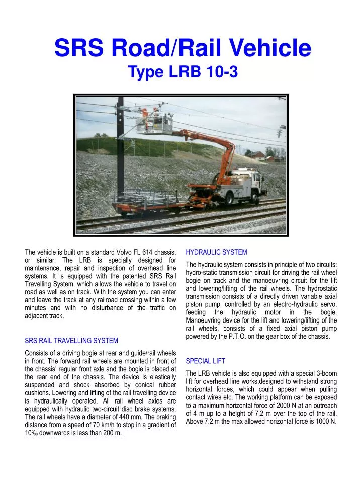
SRS Road/Rail Vehicle Type LRB 10-3.

E N D
SRS Road/Rail Vehicle Type LRB 10-3 The vehicle is built on a standard Volvo FL 614 chassis, or similar. The LRB is specially designed for maintenance, repair and inspection of overhead line systems. It is equipped with the patented SRS Rail Travelling System, which allows the vehicle to travel on road as well as on track. With the system you can enter and leave the track at any railroad crossing within a few minutes and with no disturbance of the traffic on adjacent track. SRS RAIL TRAVELLING SYSTEM Consists of a driving bogie at rear and guide/rail wheels in front. The forward rail wheels are mounted in front of the chassis’ regular front axle and the bogie is placed at the rear end of the chassis. The device is elastically suspended and shock absorbed by conical rubber cushions. Lowering and lifting of the rail travelling device is hydraulically operated. All rail wheel axles are equipped with hydraulic two-circuit disc brake systems. The rail wheels have a diameter of 440 mm. The braking distance from a speed of 70 km/h to stop in a gradient of 10‰ downwards is less than 200 m. HYDRAULIC SYSTEM The hydraulic system consists in principle of two circuits: hydro-static transmission circuit for driving the rail wheel bogie on track and the manoeuvring circuit for the lift and lowering/lifting of the rail wheels. The hydrostatic transmission consists of a directly driven variable axial piston pump, controlled by an electro-hydraulic servo, feeding the hydraulic motor in the bogie.Manoeuvring device for the lift and lowering/lifting of the rail wheels, consists of a fixed axial piston pump powered by the P.T.O. on the gear box of the chassis. SPECIAL LIFT The LRB vehicle is also equipped with a special 3-boom lift for overhead line works,designed to withstand strong horizontal forces, which could appear when pulling contact wires etc. The working platform can be exposed to a maximum horizontal force of 2000 N at an outreach of 4 m up to a height of 7.2 m over the top of the rail. Above 7.2 m the max allowed horizontal force is 1000 N.
TECHNICAL DATA Chassis: Volvo FL 614 Lift: (standard version) Diesel engine: 152 kW (207 hp) Max height: 8.5 m (from top of the rail Speed on road: 90 km/h to bottom of platform) Speed on track: 70 km/h Outreach: 5.0 (from center of track)Total length: 8.9 m Max load in platform: 350 kg or 3 personsWidth: 2.5 m Platform dimensions: 1.1 x 2 mTransport height (on track): 3.55 m hydraulic rotation ±40°Transport height (on road): 3.30 mRail wheel diameter: 440 mm P.O. Box 11 178SE-161 11 BROMMAPhone: +46 - 8 - 799 67 00Fax: +46 - 9 - 28 43 33srs.bromma@srs.scancem.com P.O. Box 1512SE-271 00 YSTADPhone: +46 - 411 - 594 00Fax: +46 - 411 - 55 57 42srs.ystad@srs.scancem.com 4/2003 SWEDISH RAIL SYSTEM AB SRS