Download
1 / 37
380 likes | 394 Views
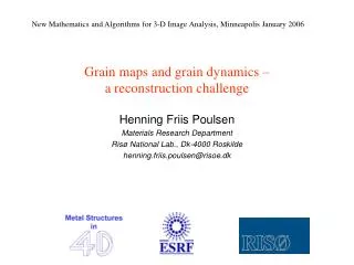
New Mathematics and Algorithms for 3-D Image Analysis, Minneapolis January 2006. Grain maps and grain dynamics – a reconstruction challenge. Henning Friis Poulsen Materials Research Department Risø National Lab., Dk-4000 Roskilde henning.friis.poulsen@risoe.dk. Polycrystals.

E N D
New Mathematics and Algorithms for 3-D Image Analysis, Minneapolis January 2006 Grain maps and grain dynamics – a reconstruction challenge Henning Friis Poulsen Materials Research Department Risø National Lab., Dk-4000 Roskilde henning.friis.poulsen@risoe.dk
Polycrystals • Bravais lattice • Group symmetry • Basis (atoms) • Orientation • Elastic Strain Phase Grain morphology
4D vision • Bulk penetration (1 mm – 1 cm). • 3D characterisation on a micron scale: • morphology • orientation • phase • plastic and elastic strain • Maps of100-1000 grains • In-situ studies ------------------------------------ H.F. Poulsen: Three-Dimensional X-ray Diffraction Microscopy (Springer, 2004).
Risø: J.R. Bowen, C. Gundlach, K. Haldrup, B. Jacobsen, D. Juul Jensen, E. Knudsen, E.M. Lauridsen, L. Margulies,S.F. Nielsen, W. Pantleon, S. Schmidt, H.O. Sørensen, J. Wert, G. Winther ESRF, ID11:A. Goetz, Å. Kvick, G. Vaughan ESRF, ID15: T. Buslaps, V. Honkimäki APS: U. Lienert, J. Almer GKSS: F. Beckmann, R.V. Martins IMSA, Lyon: W. Ludwig City Uni of N.Y.: A. Alpers, G.T. Herman, L. Rodek
Sampling strategy Position: 3D Orientation: 3D Elastic strain: 6D Plastic strain 8D Phase ? Serial data acquisition: B.C. Larson et al. (2002). Nature415, 887-890. Tomographic reconstruction: 3DXRD
Diffraction Diffraction spots: Where: Position of voxel + Symmetry + Orientation + Elastic strain Intensity: ~ volume Finite number
3DXRD set-up Area detector Detector I L = 5-10 mm Position and Orientation Detector II L = 40 cm Orientation and Strain
Grain maps • Simplifications: • Monophase • No strain • Undeformed material Morphology + Orientation CMS + Volume + Orientation Full field Layer-by- layer
W fr r 3 r 2 r l n z z’ f r y’ y x x’ Orientation space Rodrigues vector: r = n tan(j/2) Rodrigues space: Each grain: a point
W fr r 3 r 2 r l • For > 1000 grains: • Orientation • Volume • CMS Position GRAINDEX Blob-finding in orientation space: ------------------------------------------ E.M. Lauridsen, S. Schmidt, R.M. Suter, H.F. Poulsen. J. Appl. Cryst. (2001) 34, 744 .
Ferrite – Austenite: N g q g g g a a q a a dN/dt a b Phase Transformations in Carbon Steel Work with T.U. Delft ----------------------------------- S.E. Offermanet al.(2002). Science298, 1003. S.E. Offermanet al.(2004). Acta Mater.52, 4757.
Growth curves for individual grains Grain radius (mm) Annealing time (sec) Standard Avrami type models are gross simplifications
Grain Maps: grain by grain Grain map algorithms: Filtered back-projection Algebraic Reconstruction (ART)
ART for tomography Solve: Ax = b x: density of voxel b: detector pixel intensitites A: geometry of set-up Solve iteratively by Kaczmark routine: xi bj l --------------- H.F. Poulsen & X. Fu. J. Appl. Cryst 36, 1062 (2003).
Constraint on probability 0 xj 1 ART for 3DXRD Solve: Ax = b x: prob. of voxel belonging to grain b: detector pixel intensitites A: geometry of set-up Solve iteratively by Kaczmark routine: xi bj l --------------- H.F. Poulsen & X. Fu. J. Appl. Cryst 36, 1062 (2003).
Dependence on number of projections FBP ART 5 projections: 49 projections:
2D-ART: Results mm 5 min acquisition time Resolution 5 mm H.F. Poulsen, X. Fu. J. Appl.Cryst36, 1062 (2003)
Video of growth of an internal grain Recrystallization of 42% deformed pure Al during annealing at ~200 C. -------------------------- S. Schmidt, S. F. Nielsen, C. Gundlach, L. Margulies, X. Huang, D. Juul Jensen. Science305, 229 (2004)
Grain growth ------------------- Work in progress by S. Schmidt, J. Driver et al.
Hierachial solution GRAINDEX ART Discrete Monte Carlo (*) ----------------------- (*) A. Alpers, H.F. Poulsen, E. Knudsen, G.T. Herman Electron. Notes Discrete Math. 20, 419-437 (2005).
Deformation 0% 11% Grain maps in deformed case: Spot overlap
r3 r x r1 y z r Reconstruction of deformed materials: Density in 6D space: Vectorfield Eulerian space x SO(3) Challenges: Dimension Curvature Crystal symmetry Finite # projections
Detector plane Envelope surface (L, ydet, zdet) Wfr 4q r3 r2 rl xl zl Sample yl Projection lines Projection surface in 6D space Position space: Orientation space:
Reconstruct density in 6D space A: 0 xj r0 ; j, B: ; jkl. Challenge: Dimensionality size of A: 1010 x 1010 Extremely sparse H.F. Poulsen. Phil. Mag. 83, 2761 (2003).
Properties of grains • Discrete objects. • Simply-connected space filling objects • Similarity of grain maps • The grain boundaries are smooth. • Near convex • Approx. polyhedra
Tomography ID19 – ID15 3DXRD Spatial resolution 0.6 – 2.8 mm 5 mm 3DXRD + Tomography Resolving power 0.4 – 2 mm 0.1 mm Time resolution 1 min – 2 sec 0.3 sec – 1 h Multiphase materials
3DRXD + Tomography Misorientations Tomography 41.5 3.7 (a) (b) (c) 37.7 52.3 53.5 49.5 45.1 (d) (e) Ex: Grain boundary wetting Challenge: Combined reconstruction --------------------------------------------------------- Collaboration w/ W. Ludwig, D. Bellet S.F. Nielsen et al. Proc. 21st Risø Int. Symp. Mat. Science p 473 (2000)
kH k0 G 100 µm Detectors Extinction contrast tomography INSA-Lyon: W. Ludwig; Risø: E.M. Laridsen, S. Schmidt, H.F. Poulsen
W fr Extinction contrast tomography Work in progress: • + Potential for 100 nm resolution • - 1000 projections => slow • Only near-perfect grains • Fewer grains
Plastic flow in 3D by tomography Work with F. Beckmann at BW2, HASYLAB Trace position ofmarkers: + Universal + Large strains - Artifical markers Future: internal markers 1 mm markers => 1% strain resolution with 20 mm spatial resolution --------------------- S.F. Nielsen, H.F. Poulsen, F. Beckmann, F. Thorning, J.A. Wert. Acta Mater. (2003) 51, 2407.
Effect of material geometry: Displacement field: Simple deformation theory: --------------- K. Haldrup, S.F. Nielsen, F. Beckmann, J.A. Wert. Mater. Sci.Techn., 2005, in print.
Maps that completely describe the fundamental plastic flow mechanism in a 3D, bulk sample Measuring slip activity Tomography: Local plastic flow 3DXRD: Local orientation change
Total Crystallography + Grain map Phase • Examples: • Identification of new drugs • Drug distribution in tablets • Rocks, meteorites • Approach: • ”Orthogonal data” • Bootstrapping Project partners: Risø, ESRF, CUNY, Novo, Oxford, MPIbpc, IP-Prague
Summary Mission: Map {phase, orientation, elastic strain, plastic strain, …} in 4D MShard Approach: x-rays, tomographic reconstruction, 3D detector Challenges:High dimensional space; extremely sparse Gray value/discrete parameters Number of projections Strategy ?:Discrete properties Hierachial approach Hybrid models
ESRF Current beamline 50 m Spatial Resolution Present: 1 x 5 x 5 mm3 New detector (2006): 1 x 2 x 2 mm3 Nanoscope: 0.1 x 0.1 x 0.1 mm3 Operation mid 2007