Download
1 / 23
230 likes | 358 Views
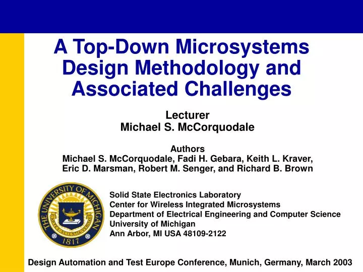
A Top-Down Microsystems Design Methodology and Associated Challenges. Lecturer Michael S. McCorquodale Authors Michael S. McCorquodale, Fadi H. Gebara, Keith L. Kraver, Eric D. Marsman, Robert M. Senger, and Richard B. Brown. Solid State Electronics Laboratory

E N D
A Top-Down Microsystems Design Methodology and Associated Challenges LecturerMichael S. McCorquodale AuthorsMichael S. McCorquodale, Fadi H. Gebara, Keith L. Kraver, Eric D. Marsman, Robert M. Senger, and Richard B. Brown Solid State Electronics Laboratory Center for Wireless Integrated MicrosystemsDepartment of Electrical Engineering and Computer Science University of Michigan Ann Arbor, MI USA 48109-2122 Design Automation and Test Europe Conference, Munich, Germany, March 2003
Outline • Motivation • Microsystems: Anatomy • Bottom-Up Design Methodology • WIMS Microcontroller • Design Framework • Top-Down Design Methodology • Gaps and Solutions • Conclusions
Motivation • Discuss design trends and challenges in microsystems technology • Leverage advances in mixed-signal SoC design automation • Determine a design methodology and framework appropriate for microsystems technology • Implement methodology in a microsystem design • Demonstrate increased design efficiency and verification • Identify gaps in tool suite and promote development of required capabilities Motivation Microsystems Bottom-Up Microcontroller Framework Top-Down Gaps & Solns. Conclusions
Microsystems: Anatomy The anatomy of a generalized wireless integrated microsystem (WIMS). Key technologies and associated development tools are shown MEMS Analog Mixed - Signal Digital/VLSI RFIC/RFMEMS Antenna Sensor ADC Sensor/Actuator Baseband Wireless Microprocessor Interface Modem Interface Actuator DAC Clock AHDL MS - HDL VHDL AHDL FE Custom Custom Synthesis Custom Tools IC Tools IC Tools Tools RFIC Tools Motivation Microsystems Bottom-Up Microcontroller Framework Top-Down Gaps & Solns. Conclusions
Microsystems: Anatomy The anatomy of a generalized wireless integrated microsystem (WIMS). Key technologies and associated development tools are shown MEMS Analog Mixed - Signal Digital/VLSI RFIC/RFMEMS Antenna Sensor ADC Sensor/Actuator Baseband Wireless Microprocessor Interface Modem Interface Actuator DAC Clock AHDL MS - HDL VHDL AHDL FE Custom Custom Synthesis Custom Tools IC Tools IC Tools Tools RFIC Tools Motivation Microsystems Bottom-Up Microcontroller Framework Top-Down Gaps & Solns. Conclusions
Microsystems: Anatomy The anatomy of a generalized wireless integrated microsystem (WIMS). Key technologies and associated development tools are shown MEMS Analog Mixed - Signal Digital/VLSI RFIC/RFMEMS Antenna Sensor ADC Sensor/Actuator Baseband Wireless Microprocessor Interface Modem Interface Actuator DAC Clock AHDL MS - HDL VHDL AHDL FE Custom Custom Synthesis Custom Tools IC Tools IC Tools Tools RFIC Tools Motivation Microsystems Bottom-Up Microcontroller Framework Top-Down Gaps & Solns. Conclusions
Microsystems: Anatomy The anatomy of a generalized wireless integrated microsystem (WIMS). Key technologies and associated development tools are shown MEMS Analog Mixed - Signal Digital/VLSI RFIC/RFMEMS Antenna Sensor ADC Sensor/Actuator Baseband Wireless Microprocessor Interface Modem Interface Actuator DAC Clock AHDL MS - HDL VHDL AHDL FE Custom Custom Synthesis Custom Tools IC Tools IC Tools Tools RFIC Tools Motivation Microsystems Bottom-Up Microcontroller Framework Top-Down Gaps & Solns. Conclusions
Microsystems: Anatomy The anatomy of a generalized wireless integrated microsystem (WIMS). Key technologies and associated development tools are shown MEMS Analog Mixed - Signal Digital/VLSI RFIC/RFMEMS Antenna Sensor ADC Sensor/Actuator Baseband Wireless Microprocessor Interface Modem Interface Actuator DAC Clock AHDL MS - HDL VHDL AHDL FE Custom Custom Synthesis Custom Tools IC Tools IC Tools Tools RFIC Tools Motivation Microsystems Bottom-Up Microcontroller Framework Top-Down Gaps & Solns. Conclusions
Bottom-Up Design Methodology Verification: DRC, LVS (Top Routing Only), Parasitic Extraction Verification: DRC, LVS (Top Routing Only), Parasitic Extraction and and Backannotation Backannotation Tapeout Tapeout (IC Tool) (IC Tool) Macro Automatic Place and Route Macro Automatic Place and Route (APR and IC Tool) (APR and IC Tool) Digital Macro Digital Macro Analog Macro Analog Macro Mechanical Macro Mechanical Macro Digital Domain Digital Domain Analog Domain Analog Domain Mechanical Domain Mechanical Domain Synthesis/APR/Timing Synthesis/APR/Timing Analog Physical Design Analog Physical Design (Synthesizer) (Synthesizer) (IC Tool) (IC Tool) Digital Digital Library Library Digital Design Digital Design Custom Analog Design Custom Analog Design Custom Mechanical Design Custom Mechanical Design (HDL) (HDL) (SPICE) (SPICE) (FE) (FE) Process Process Digital Specification Digital Specification Analog Specification Analog Specification Mechanical Specification Mechanical Specification Library Library System Specification and Design Partition System Specification and Design Partition Motivation Microsystems Bottom-Up Microcontroller Framework Top-Down Gaps & Solns. Conclusions
Bottom-Up Design Methodology Verification: DRC, LVS (Top Routing Only), Parasitic Extraction Verification: DRC, LVS (Top Routing Only), Parasitic Extraction and and Backannotation Backannotation Tapeout Tapeout (IC Tool) (IC Tool) Macro Automatic Place and Route Macro Automatic Place and Route (APR and IC Tool) (APR and IC Tool) Digital Macro Digital Macro Analog Macro Analog Macro Mechanical Macro Mechanical Macro Digital Domain Digital Domain Analog Domain Analog Domain Mechanical Domain Mechanical Domain Synthesis/APR/Timing Synthesis/APR/Timing Analog Physical Design Analog Physical Design (Synthesizer) (Synthesizer) (IC Tool) (IC Tool) Digital Digital Library Library Digital Design Digital Design Custom Analog Design Custom Analog Design Custom Mechanical Design Custom Mechanical Design (HDL) (HDL) (SPICE) (SPICE) (FE) (FE) Process Process Digital Specification Digital Specification Analog Specification Analog Specification Mechanical Specification Mechanical Specification Library Library System Specification and Design Partition System Specification and Design Partition Motivation Microsystems Bottom-Up Microcontroller Framework Top-Down Gaps & Solns. Conclusions
Bottom-Up Design Methodology Verification: DRC, LVS (Top Routing Only), Parasitic Extraction Verification: DRC, LVS (Top Routing Only), Parasitic Extraction and and Backannotation Backannotation Tapeout Tapeout (IC Tool) (IC Tool) Macro Automatic Place and Route Macro Automatic Place and Route (APR and IC Tool) (APR and IC Tool) Digital Macro Digital Macro Analog Macro Analog Macro Mechanical Macro Mechanical Macro Digital Domain Digital Domain Analog Domain Analog Domain Mechanical Domain Mechanical Domain Synthesis/APR/Timing Synthesis/APR/Timing Analog Physical Design Analog Physical Design (Synthesizer) (Synthesizer) (IC Tool) (IC Tool) Digital Digital Library Library Digital Design Digital Design Custom Analog Design Custom Analog Design Custom Mechanical Design Custom Mechanical Design (HDL) (HDL) (SPICE) (SPICE) (FE) (FE) Process Process Digital Specification Digital Specification Analog Specification Analog Specification Mechanical Specification Mechanical Specification Library Library System Specification and Design Partition System Specification and Design Partition Motivation Microsystems Bottom-Up Microcontroller Framework Top-Down Gaps & Solns. Conclusions
Bottom-Up Design Methodology Verification: DRC, LVS (Top Routing Only), Parasitic Extraction Verification: DRC, LVS (Top Routing Only), Parasitic Extraction and and Backannotation Backannotation Tapeout Tapeout (IC Tool) (IC Tool) Macro Automatic Place and Route Macro Automatic Place and Route (APR and IC Tool) (APR and IC Tool) Digital Macro Digital Macro Analog Macro Analog Macro Mechanical Macro Mechanical Macro Digital Domain Digital Domain Analog Domain Analog Domain Mechanical Domain Mechanical Domain Synthesis/APR/Timing Synthesis/APR/Timing Analog Physical Design Analog Physical Design (Synthesizer) (Synthesizer) (IC Tool) (IC Tool) Digital Digital Library Library Digital Design Digital Design Custom Analog Design Custom Analog Design Custom Mechanical Design Custom Mechanical Design (HDL) (HDL) (SPICE) (SPICE) (FE) (FE) Process Process Digital Specification Digital Specification Analog Specification Analog Specification Mechanical Specification Mechanical Specification Library Library System Specification and Design Partition System Specification and Design Partition Motivation Microsystems Bottom-Up Microcontroller Framework Top-Down Gaps & Solns. Conclusions
Bottom-Up Design Methodology Verification: DRC, LVS (Top Routing Only), Parasitic Extraction Verification: DRC, LVS (Top Routing Only), Parasitic Extraction and and Backannotation Backannotation Tapeout Tapeout (IC Tool) (IC Tool) Macro Automatic Place and Route Macro Automatic Place and Route (APR and IC Tool) (APR and IC Tool) Digital Macro Digital Macro Analog Macro Analog Macro Mechanical Macro Mechanical Macro Digital Domain Digital Domain Analog Domain Analog Domain Mechanical Domain Mechanical Domain Synthesis/APR/Timing Synthesis/APR/Timing Analog Physical Design Analog Physical Design (Synthesizer) (Synthesizer) (IC Tool) (IC Tool) Digital Digital Library Library Digital Design Digital Design Custom Analog Design Custom Analog Design Custom Mechanical Design Custom Mechanical Design (HDL) (HDL) (SPICE) (SPICE) (FE) (FE) Process Process Digital Specification Digital Specification Analog Specification Analog Specification Mechanical Specification Mechanical Specification Library Library System Specification and Design Partition System Specification and Design Partition Motivation Microsystems Bottom-Up Microcontroller Framework Top-Down Gaps & Solns. Conclusions
Bottom-Up Design Methodology The Problems • No opportunity for architectural studies • Time-consuming design iteration • Cross-domain verification at top level only • Time-consuming system level simulation, if it is even possible Motivation Microsystems Bottom-Up Microcontroller Framework Top-Down Gaps & Solns. Conclusions
Die micrograph of the fabricated microsystem WIMS Microcontroller • TSMC 0.18 micron mixed-mode • 16-bit 3-stage pipeline core • Analog front end (AFE) • MEMS-based clock generator • 64KB on-chip SRAM • Timer and serial interfaces • 1.5 million transistors • 10.24mm2 Motivation Microsystems Bottom-Up Microcontroller Framework Top-Down Gaps & Solns. Conclusions
Design Framework: Requirements • System level simulation support (HDL) • Cross-domain verification at any level for MEMS, analog, and digital electronics • Finite element simulation • Active device and HDL simulation • Parasitic extraction • Co-simulation of primitives and HDL • Timing verification • HDL synthesis • Automatic place and route Motivation Microsystems Bottom-Up Microcontroller Framework Top-Down Gaps & Solns. Conclusions
Design Framework: Employed • Cadence AMSSystem modeling, primitive/HDL co-simulation, and MEMS modeling • SpectreAnalog device level simulation • CoventorwareFinite element analysis • SynopsysDigital synthesis • Cadence Silicon EnsembleAutomatic place and route • Mentor Graphics CalibreDRC, ERC, and LVS Motivation Microsystems Bottom-Up Microcontroller Framework Top-Down Gaps & Solns. Conclusions
Top-Down Design Methodology Abstract System Model ( Verilog - AMS: Verilog and Verilog - A) Digital Model Analog Model Mechanical Model ( Verilog ) ( Verilog - A) ( Verilog - A) Digital Domain Analog Domain Behavioral Verification Custom Analog Design Mechanical Design Mechanical Domain ( Verilog ) (SPICE) (Finite Element) Cross - Domain Verification ( Verilog with updated Verilog - A from achieved performance and/or Verilog and Verilog - A with Primitives) Synthesis/APR/Timing Physical Design/Verif. Physical Design/Verif. (Synthesis Tool) (IC Tool) (IC Tool) Process Library Extraction, Timing Parasitic Extraction Parasitic Extraction Digital (Timing Tool) (IC Tool) (IC Tool) Library Cross - Domain Verification ( Verilog with updated Verilog - A from parasitics and/or Verilog and Verilog - A with Primitives) Digital Macro Analog Macro Mechanical Macro Macro Place and Route, Layout Verification: DRC, LVS (APR and IC Tool) Layout Parasitic Extraction (LPE) and Backannotation (IC Tool) Tapeout Cross - Domain Verification ( Verilog with updated Verilog - A with interconnect parasitics ) Motivation Microsystems Bottom-Up Microcontroller Framework Top-Down Gaps & Solns. Conclusions
Top-Down Design Methodology Abstract System Model ( Verilog - AMS: Verilog and Verilog - A) Digital Model Analog Model Mechanical Model ( Verilog ) ( Verilog - A) ( Verilog - A) Digital Domain Analog Domain Behavioral Verification Custom Analog Design Mechanical Design Mechanical Domain ( Verilog ) (SPICE) (Finite Element) Cross - Domain Verification ( Verilog with updated Verilog - A from achieved performance and/or Verilog and Verilog - A with Primitives) Synthesis/APR/Timing Physical Design/Verif. Physical Design/Verif. (Synthesis Tool) (IC Tool) (IC Tool) Process Library Extraction, Timing Parasitic Extraction Parasitic Extraction Digital (Timing Tool) (IC Tool) (IC Tool) Library Cross - Domain Verification ( Verilog with updated Verilog - A from parasitics and/or Verilog and Verilog - A with Primitives) Digital Macro Analog Macro Mechanical Macro Macro Place and Route, Layout Verification: DRC, LVS (APR and IC Tool) Layout Parasitic Extraction (LPE) and Backannotation (IC Tool) Tapeout Cross - Domain Verification ( Verilog with updated Verilog - A with interconnect parasitics ) Motivation Microsystems Bottom-Up Microcontroller Framework Top-Down Gaps & Solns. Conclusions
Top-Down Design Methodology Abstract System Model ( Verilog - AMS: Verilog and Verilog - A) Digital Model Analog Model Mechanical Model ( Verilog ) ( Verilog - A) ( Verilog - A) Digital Domain Analog Domain Behavioral Verification Custom Analog Design Mechanical Design Mechanical Domain ( Verilog ) (SPICE) (Finite Element) Cross - Domain Verification ( Verilog with updated Verilog - A from achieved performance and/or Verilog and Verilog - A with Primitives) Synthesis/APR/Timing Physical Design/Verif. Physical Design/Verif. (Synthesis Tool) (IC Tool) (IC Tool) Process Library Extraction, Timing Parasitic Extraction Parasitic Extraction Digital (Timing Tool) (IC Tool) (IC Tool) Library Cross - Domain Verification ( Verilog with updated Verilog - A from parasitics and/or Verilog and Verilog - A with Primitives) Digital Macro Analog Macro Mechanical Macro Macro Place and Route, Layout Verification: DRC, LVS (APR and IC Tool) Layout Parasitic Extraction (LPE) and Backannotation (IC Tool) Tapeout Cross - Domain Verification ( Verilog with updated Verilog - A with interconnect parasitics ) Motivation Microsystems Bottom-Up Microcontroller Framework Top-Down Gaps & Solns. Conclusions
Top-Down Design Methodology Abstract System Model ( Verilog - AMS: Verilog and Verilog - A) Digital Model Analog Model Mechanical Model ( Verilog ) ( Verilog - A) ( Verilog - A) Digital Domain Analog Domain Behavioral Verification Custom Analog Design Mechanical Design Mechanical Domain ( Verilog ) (SPICE) (Finite Element) Cross - Domain Verification ( Verilog with updated Verilog - A from achieved performance and/or Verilog and Verilog - A with Primitives) Synthesis/APR/Timing Physical Design/Verif. Physical Design/Verif. (Synthesis Tool) (IC Tool) (IC Tool) Process Library Extraction, Timing Parasitic Extraction Parasitic Extraction Digital (Timing Tool) (IC Tool) (IC Tool) Library Cross - Domain Verification ( Verilog with updated Verilog - A from parasitics and/or Verilog and Verilog - A with Primitives) Digital Macro Analog Macro Mechanical Macro Macro Place and Route, Layout Verification: DRC, LVS (APR and IC Tool) Layout Parasitic Extraction (LPE) and Backannotation (IC Tool) Tapeout Cross - Domain Verification ( Verilog with updated Verilog - A with interconnect parasitics ) Motivation Microsystems Bottom-Up Microcontroller Framework Top-Down Gaps & Solns. Conclusions
Gaps and Solutions Gaps in the Tool Suite MEMS and analog simulation results not automatically extracted to behavioral model Lack of physical verification for MEMS components No synthesis capabilities for MEMS and analog subsystems from topological or behavioral models Inability to port designs between process technologies Solutions: Future Direction Custom and manual extraction: Requires design automation Custom mod. of DRC/LVS decks: Requires support No current solution: Requires design automation No current solution: Requires design automation Motivation Microsystems Bottom-Up Microcontroller Framework Top-Down Gaps & Solns. Conclusions
Conclusions • Microsystem design methodologies are in their infancy • Current methodologies have originated from the disparate nature of the technology • The proposed top-down methodology leverages advances in mixed-signal design automation • The proposed methodology is efficient and offers superior verification as compared to current methodologies • Gaps in tool suites exist and must be addressed for future microsystems developments • Tool suites are disparate and can be built into a single framework Motivation Microsystems Bottom-Up Microcontroller Framework Top-Down Gaps & Solns. Conclusions